Ruthless Pursuit of Power: The Mystique of the C6 Corvette LS7 Engine - Page 14 of 26
Ruthless Pursuit of Power: Lucky Seven Edition: The Mystique of the 7-Liter, 7000-RPM, LS7 - Page 14 of 26
 |
 |
by Hib Halverson
© May 2013— Updated: November 2014
No use without permission, All Rights Reserved
"We had to make a change and going to a thicker-head steel valve wasn't an option," Hicks continued, "because we wanted a 7000 RPM red line. We looked at a couple of alternatives--some really kind of radical. ultra-light steel valves. I tested a few of those and they failed miserably. Then we said, 'Alright. We gotta do what ever it takes.' We went to the titanium for mass and strength because, with the titanium head, you could go to a flat, almost no cup on the combustion face--make a nice, thick section through there--and not take a big mass penalty, so you end up with a lighter valve which is also strong. (The LS7 intake) was the first production application for Del West and the largest diameter titanium valve in any production engine."
Making Ti Valves
by Hib Halverson
© May 2013— Updated: November 2014
No use without permission, All Rights Reserved
In researching titanium intake valves, I learned that not only was the LS7 their first use in a production engine, it remains the only one. There are some limited production motorcycles using them. Toyota tried Ti valves, done with powered metal technology, in limited production Lexus applications in the early-'00s but that didn't end well. Other OE's in the high-end engine market are said to be developing them, but currently, only General Motors is using a Ti valve in a production car.
Full Story: Making Ti Valves
The same protective, "CrN" coating used on the connecting rods is on the intake valves but getting that coating just right was a tough task for Jim Hicks and the engineers at GM and Del West working on the LS7 valvetrain. One of the issues they had to address was a "Ti dust wear" problem, similar in nature to what afflicted the connecting rod development. When the CrN coating wasn't right, it would fail and highly-abrasive Ti dust would develop between the valve stem and guide causing rapid guide wear. "Developing the stem coating which was going to work well with our production-style, PM guides was another challenge. Most racers use bronze guides or some other type of aftermarket guide which is cost-prohibitive. A moly-sprayed stem, which is typically used a lot on titanium valves (for racing), is very expensive. We wanted to come up with an alternative, so we worked on a chrome-nitride, vapor deposition coating. It took a little development, but it worked out really well for us. It was more cost-effective and just as good or better than the moly spray. There's some tricks to that process and we worked with Del West in developing them. The parts need to be very, very clean. The right processing steps need to be used. The coating thickness is very important and needs to be maintained to a tight tolerance. I think Del West is using it now for some of their aftermarket parts, too."
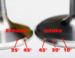
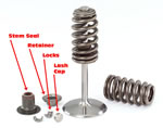
The intake valve faces are machined at 45°, 30° and 10° and this is done before the CrN coating is applied because the coating also enhances the durability of faces of the titanium valves. Typical of Ti valves, tool steel "lash caps" are used on the ends of the stems. "We actually tried to get away without a lash cap," Jim Hicks said, "and do a welded on, steel 'wafer' which was another development program. We were trying to friction weld it. You can do it, but it's not consistent enough and you can have some which come apart. That program was unsuccessful, so we ended up just using a conventional lash cap, like they use on racing engines."
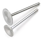
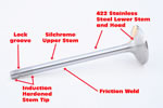
LS7 exhaust valves use the sodium-filled, hollow-stem design proven with the LS6. Its lower half is 422 stainless steel and the upper half is Silchrome. They weigh 74 grams, about 18% less than an equivalent solid stem valve. The exhaust valves in early engines were made by Eaton. In May of 2008, a new manufacturer was selected, Mahle's Edival subsidiary, but the design of the valve remained the virtually same with only slight differences due to the new supplier's manufacturing methods.
Most believe the LS7 exhaust valve's sodium-filled stem is to reduce the valve's operating temperature the way sodium-cooled valves do in severe-duty applications, such as turbo-supercharged engines. Reality is, as Jim Hicks told us, "The LS7 didn't need sodium-cooled valves due to high exhaust gas temperature. In fact, a standard (solid stem) valve could have been used if that was the only consideration. What drove the hollow stem was mass reduction to enable the 7000 rpm capability, however, once you remove much of the heat conduction path from the center of the valve, the remaining material operates at a higher temperature. By transferring some of the heat away from the valve head area and up into the guide, the sodium cooling brings the critical part of the valve - the blend between the tulip area and stem - back down to the normal operating temperature."
The 18% mass reduction gained with the hollow stem is a reliability/durability necessity at the LS7's upper rpm range. Air transfers heat very poorly, so the head of a "dry" or "air-filled" hollow stem valve would have overheated because the heat transfer path up the stem was restricted compared to that of a solid-stem valve. Partially filling the stem with sodium still has the overall mass of the valve less than a solid stem part, but ensures proper heat transfer such that the valve head's operating temperature is similar to or less than that of a heavier, solid stem valve.
Sodium melts at 208o F. In a running engine, once the exhaust valve warms past that point, inertia forces resulting from reciprocating valve movement cause the liquid sodium to circulate inside the stem, transferring heat from the valve head upward, into the stem.
To make a sodium-cooled valve, the upper part of stem is gun drilled from the bottom up. The lower part of the valve is drilled from the top down then filled with sodium paste. After that, the two parts are joined, about halfway up the stem, with a friction weld. To make the friction weld, as Jim Hicks told us, "One part is rotated at very high speed while the other half, which is stationary, is pushed into it. The friction (quickly) creates very high temperature, melting the steel and welding the two parts together. The weld, also, seals the (sodium) cavity. It's a surprisingly fast process and the heat is very localized to the interface. By the time any significant heat hits the sodium, the cavity is already sealed.
After friction welding, the stem and lock groove are machined then the tip of the valve stem is induction-hardened to provide a good wear surface for the rocker arm tip. Finally, exhaust face angles, 45° and 25°, are ground.
Both valves move in powdered metal guides. General Motors and other manufacturers have used powdered metal (PM) guides in all different engines for many years for two reasons: 1) they are more durable than either bronze or cast iron guides and 2) they are more cost effective because PM technology eliminates the need to manufacture them by metal removal (machining) processes.
"Powdered metal" describes the raw material rather than the finished product. A metal powder - primarily low alloy steel but, also, containing small amounts of manganese, copper, bronze, phosphorous, graphite along with a solid lubricant - is compressed, or "briquetted" as Dennis Gerdeman told us, under high pressure to form round stock. It is then is heated to near melting such that the powder bonds - a process known as "sintering." The round stock cools, then is cut to length and drilled. During the cylinder head machining process at Linamar, the PM guides are pressed into place and their bores are finished.
Like bronze guides, because of their copper, bronze, phosphorous and graphite components, PM guides have inherent lubricity. They are more durable because the material is harder than bronze alloys used in the guides popular with the aftermarket cylinder head service industry for installation in LS7 and other GM aluminum heads.
The LS7 uses unique valve springs. They are the typical GM "beehive" design, but they are 0.160-in. taller than all the Gen 3/4 springs GM used previously. The extra height is to accommodate the LS7's greater valve lift. These springs have 16-lbs more open pressure, too.
To get to the 7100-RPM red line such that the Z06 could go 0 to 60 in first gear required more than just "light-weighting" the valvetrain on the valve side of the rocker. It had to be as stiff as possible on the pushrod side. The pushrods are steel but, compared to other Small-Block pushrods, are larger in diameter, have more wall thickness, and to accommodate the taller head, greater length. Obviously, all that makes for a heavier pushrod, but, from a performance perspective, there is a greater benefit in keeping the pushrod side as stiff as possible, as opposed to as light as possible.
 |
 |

