Ruthless Pursuit of Power: The Mystique of the C6 Corvette LS7 Engine - Page 12 of 26
Ruthless Pursuit of Power: Lucky Seven Edition: The Mystique of the 7-Liter, 7000-RPM, LS7 - Page 12 of 26
 |
 |
by Hib Halverson
© May 2013— Updated: November 2014
No use without permission, All Rights Reserved
Judy Jin, Design Release Engineer for the LS7 cylinder head from late-2011 to mid-2014, told us that two different valve seats are used. The intake seat is made of a specific material, PMF 28, which is compatible with the titanium intake valve. The seat couldn't be too hard because, once you wear through the titanium valve's hard-faced coating and into the softer, but very abrasive titanium below, both parts fail in short order. You have to protect that coating, but still have a seat that's hard enough to avoid valve seat recession. Since they had never done titanium intakes before, the cylinder head team consulted with Federal-Mogul, seat insert supplier for other aluminum Gen 3/4 heads, and leveraged F-M's experience with titanium valves for racing. Actually, the first material F-M recommended and GM tested, PMF 28, turned out to be the one which worked.
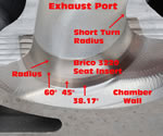
The exhaust valve seat, also supplied by F-M, is Brico 3220, used in a variety of GM aluminum heads. The Small-Block does not have coolant flowing completely around the valve seat inserts. Because of the siamesed valve seats, there's no cooling at all in the "valve bridge" between the ports. When things get extra hot, you want rapid transfer of heat away from the valves and seats and into the water jacket. For that reason, the exhausts use "copper-infiltrated" seat inserts. Federal-Mogul, takes a powdered metal blank and puts a copper cap over it. They run it though an oven, the copper melts and wicks into the microscopic voids in the powdered metal. The copper-infiltrated seats improve heat transfer out of the valves, through the seats and into the water jacket by 4-6%.
Ms. Jin added that, because the valve centerlines are so close, the valve seat installation at Linamar is a multi-step process, most of which is done in the five-axis CNC set-up which, also, machines all other critical features of the head. First, a separate CNC cuts a small "scallop" into each intake seat insert. Next, during the head's main CNC session, the seat pockets are cut such that they overlap slightly, creating the siamesed appearance. The round exhaust seats are installed into the head's exhaust seat pockets and, finally, each intake seat insert is installed with its scallop fitting over the side of the adjacent, exhaust seat insert. This process eliminates any “bi-metal” machining of the pockets which would occur if the exhaust insert was installed into the head, first. This is the preferred process because the seat pocket tooling produces the highest quality results if it cuts only aluminum.
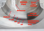
After the seats are installed, they are machined to the proper angles. On the all-important intake, starting at the combustion chamber roof, the seat angles are: 39°, 45°, 60° and 71.83° followed by a radius. The exhaust seats are cut with 38.17°, 45° and 76° angles, then a radius. In both cases, the valve contacts the seat on the 45° portion. Each seat and radius are machined by one milling tool in a single plunge movement of the 5-axis CNC's table.
The internal structure and the cooling jackets of the LS7 head are much the same as that of other Gen 3/4 heads going back to the LS1. "Nothing special in the cooling jackets compared to other Gen 3/4s. You try to get the coolant as close as you can everywhere else on the back side of the chamber," Dennis Gerdeman told us, "but you still have to have very large fillets to handle the high combustion pressures. It's structural integrity vs. cooling, so you have to strike a balance between the two. Nothing different though than the other Gen heads. They all have that same balance."
Even seemingly minor features can be of utmost importance, such as the small horizontal pad in each combustion chamber next to the spark plug. "Those are 'locators,'" Dennis told us. "When the casting is first set-up for the initial machining operation, they need locators. Each chamber has one because you want them all to be common (have the same displacement), but we use the pads in two end chambers and a horizontal pad on the intake side of the deck face as the initial locating points for the machining operations. We don't machine them away because, if we ever have an issue identified later on and believe it's a casting issue, we want to be able to go back to the cast locators and take CMM (coordinate measuring machine) measurements."
Linamar also assembled the heads then shipped them to the PBC. When you see one of these heads before it goes on an engine, you'll marvel at its appearance and feel. Its huge, glittering, CNC'ed ports, gleaming titanium intake and stainless steel exhaust valves and the shimmering, silvery combustion chamber walls are sweet eye candy for we engine guys. "The appearance of the CNC work is a balance between cycle time and surface finish," Dennis Gerdeman commented. "Ideally, you'd want to make it smoother but when it really came down to it, the gains were marginal at best. The cycle time already is so long. When you consider you have to do eight ports and four chambers and all the seat machining, it's a lot of time in the machine. Each head takes about two hours."
Even the exterior surfaces of the heads have a "premium" look and feel because of the semi-permanent mold process used to cast them. Like the crankshaft, the LS7 head is one of those parts that's just too damn pretty to be run on an engine. All and all, it's a high-tech piece both in performance and appearance. An interesting bottom line on the LS7 head comes when one compares its airflow numbers with those of the head on the base Corvette engine of that period, the LS2. In a straight-across comparison, the LS7 head flows about 25% more air. When compared to the '08-'13 base LS3, it's 20% more. Either way, it's a huge improvement.
We asked Dennis Gerdeman, if he could revisit the LS7 head design, today, what he'd do differently. "From an analysis standpoint, our tools have improved significantly over what we had back when we developed this cylinder head," Gerdeman replied. "I would probably play with valve sizes, again, and locations within the chamber just to see if there's a little more we could squeak out of this from an airflow perspective. I don't think it would change significantly, but we may have ended up with a little larger exhaust--maybe a slightly smaller intake. It may even have led to a slightly different intake port shape with a different area schedule.
"Those are probably the two things I'd like to revisit: the intake port and small tweaks to the valve sizes or centers, because with the tools we have today, you can accomplish that in hours instead of weeks. Before you had to make a CAD model, send it to a job shop and have them cut you a flow box then, flow it on the bench and try again. Now we can do it with analysis in a fraction of the time."
Dennis and I ended our LS7 cylinder head discussion talking about how the engine's mystique comes from the power it makes without boost and its drivability. "When you think what you can pull out of a Small-Block naturally-aspirated--making that 500-hp--it's pretty amazing," was his final observation.
 |
 |


