
The newest player in the intake manifold market is MSD, LLC. With its “Atomic Air Force” line of Nylon 6 manifolds for GM’s Generation 3, 4 and 5 Small-Block V8s, MSD is continuing its branch-out from being just an ignition parts maker, which began in 1995, with the company’s expansion into aftermarket EFI parts, and continued in 2010 with complete, aftermarket EFI systems. Further widening of MSD’s induction horizons began in 2015 with the company’s acquisition by Holley, the carburetor and fuel injection manufacturer.
The first one of these manifolds, released by MSD at the beginning of 2015, fits the LS7 engine used in 2006-2013 Corvette Z06es and 2014-2015 Camaro Z/28s. The first test results released to the public came in late 2014 from Lingenfelter Performance Engineering. LPE’s engine dyno tests were done with a modified LS7 and revealed MSD’s new LS7 manifold to be capable of substantial performance gains over the production manifold and modest gains over its only competition in the market, the intake sold by FAST. Once the “AAF” was in the hands of other engine builders, additional evidence of the manifold’s performance enhancing ability with modified LS7s supported the initial testing done at Lingenfelter’s.
What’s been lacking is good test data on what effect, if any, changing to MSD’s Atomic Air Force has on a near stock LS7. The CAC decided to look into that. Prior to our AAF installation and testing, we interviewed the Engineering Consultant for the Atomic Air Force LS7 project, Caleb Newman, in the Spring of 2015.
Corvette Action Center: What was the most important design feature of the LS7 manifold?
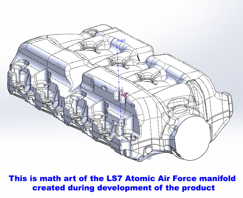
Caleb Newman: Our primary goal was to increase plenum volume and reduce geometric constraints for air to get to the bell-mouth (the intake port entry), eliminate the 90-degree turn right at the bell for improved flow development and peak flow capacity and better optimize the tuned length (of the port). Incredible attention to detail was required to balance this with manufacturing.


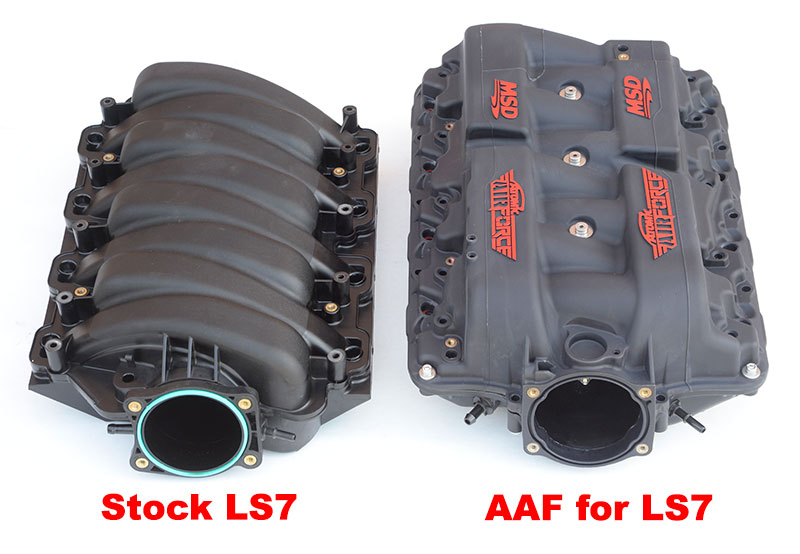
CAC: There is a significant difference in the appearance of the LS7 AAF manifold compared to the stock manifold. Why is that?
CN: I coined the term “plenum rails” to identify the unique shape. The intent was to allow air over the opposing runner enabling a straighter runner to pull from 360 degrees around the bell.
 CAC: Compared to aluminum, the capital investment for tooling to make “plastic” intake manifolds is huge, but, once the tooling is built, the cost to manufacture the part is much less, whereas, the tooling costs for aluminum are less but it costs a lot to make aluminum manifolds. Why did MSD opt to take the expensive route, up front, and buy the tooling to do the manifold in plastic?
CN: The heat soak and subsequent losses from using aluminum would be unacceptable to performance and the weight penalty is huge. The unit cost for the same design would also be fairly high in aluminum because of the runner in a box construction (meaning: runners are not formed by the plenum wall anywhere). Given the market this was never deemed acceptable. A glass-filled, nylon 6 was the only consideration from the start. It is the right way to do this product.
CAC: I assume that MSD did comparative flow testing of the OE LS7 vs the Atomic Air Force.
CN: I did extensive CFD (computational fluid dynamics) analysis. In general I don’t put much weight on flow bench numbers for an intake manifold. It is a small indicator but it is not the limiting factor–unless you really mess up!. And flow bench work doesn’t account for tuning effects. In CFD we analyze flow numbers against stock, but again only as a small indicator because it is available. The tool is best suited to identify flow development and acceleration gradients across the flow path. We are looking for flow separation points, pinched geometry and the smoothest acceleration through the runner. Incredibly small details have a large affect when analyzing this way. It is, however, a bit more qualitative than quantitative when viewed this way.
CAC: I know MSD worked with Lingenfelter which tested the intake on a modified LS7. I’m more interested in less modified engines right now. What projections does the AAF LS7 Development Team have for those installing that manifold on a stock or near stock engine with no cam change, no head work, stock throttle body and stock exhaust?
CN: We started testing at MSD and I laid out a full test plan, including complete OE configuration including cam and production exhaust manifolds with OE catalytic converters. It did not have a full front drive, however corrected for SAE J1349, the numbers were representative of a stock engine. We tested 2 prototypes of the AAF with configurations for 4 runner lengths and to quantify any difference from the dip required for a stock fuel rail. We ran 90 and 102mm throttle bodies and proved appreciable gains with the larger throttle vs. none on competitive manifolds. We, also, benchmarked the stock intake as well as competitive manifolds. We, then, repeated all the tests adding headers and retaining the stock cam. Then, the cam was changed and all tests repeated again.
Generally, we saw 20HP and 30 lb/ft torque gains in the stock configuration and numbers grew from there as other components were added (net gains from intake only–all other factors identical). Numbers hit around 30HP and 20+ lb/ft torque with the cam added. Interesting enough the OE cam and headers had the greatest torque gain–better than the cammed version (and stock exhaust). We maintained a common target A/F (air:fuel rato) on all tests and controlled oil and water temperatures at the start of every run. All testing was completed to SAE J-607 correction factor.
I enlisted my industry colleagues at LPE and introduced them to MSD to obtain 3rd party development from someone with rigorous testing acumen. I did the same with Katech, Inc. on the (C7) LT1 testing. We performed both engine and chassis dyno testing on a mild LS7 and extreme LS7 respectively. The gains on the engine dyno were comparable to the engine dyno testing at MSD. The incredible gains were on the Lingenfelter L28 Camaro on the chassis dyno. I was at LPE when they ran the test and we were floored, dug through the data to be sure nothing was wrong and repeated the test multiple times with the same results. The intake responds well on stock configuration and very well to more aggressively built engines that other 3rd party companies are finding in their own independent tests.
CAC: Last question: Compared to the ’08-’13 LS3 and the ’14-’16 Corvette’s LT1, the LS7s production volume was rather small and, thus, has a comparatively much smaller market. What prompted MSD to pick the LS7 as the first engine for which to release an “AAF” intake, rather than the LS3 or the LT1?
CN: It was widely known that current aftermarket intakes don’t generally produce improvements on the LS3 so it was not in the original plan. It was only added for development after the LS7 far exceeded targets. Outside of LS3, the LS7 is a big market. After testing some prototypes using the same LS7 strategy and feature constraints MSD wanted, we made good power but gave up what we felt was too much torque to get it. The LS3 manifold released has been postponed until we have a design which will make good power without the expense of mid-range torque.
The Corvette Action Center also interviewed MSD President Russell Stephens at the SEMA Show in November of 2015.
CAC: What prompted MSD to get into the intake manifold business:
Russell Stephens We looked at what the opportunities were (to expand our product line). Then, we looked at what products were in the LS intake manifold market. There was only one manufacturer in that market–there was no real competitors there. We had the right resources and the right people and we felt there were some improvements we could make in that (LS7) intake manifold which would offer better performance.
CAC: How did you find Caleb Newman?
RS: We knew the right people and engaged him as a consultant on the design.
CAC: Did he work with you on all the manifolds or just the one for the LS7.
RS: He worked with us on all the manifolds.
CAC: Why did you decide launch the Atomic Air Force product line with a manifold for the LS7?
RS: (laughs)A lot of people have asked that. It’s the smaller amount of volume but that’s the one which gets the most attention. It’s what everybody aspires to–the LS7. Also, through our research and testing of stock parts, we determined there were some very good gains to be made from an LS7 intake manifold.
CAC: What about the new LT1 and the LS1 and LS6?
RS: They are available now, the LT1 along with the LS1, -2 and -6. The only one that we not shipping is the LS3. We couldn’t meet the performance goals we set so development on an LS3 version continues.
CAC: I heard you are planning to obtain a California Air Resources Board “EO” number for the LS7 intake.
RS: We haven’t started down that path, but we eventually will.
CAC: When you begin that part of the project, are you going to work in SEMA’s new emissions test laboratory which just opened?
RS: More than likely but we also have some other labs we can go though to do that testing.
(Webmaster note: at the time this article was posted on the CAC in mid-Feb. 2016, MSD had begun the testing necessary to earn CARB’s EO number.
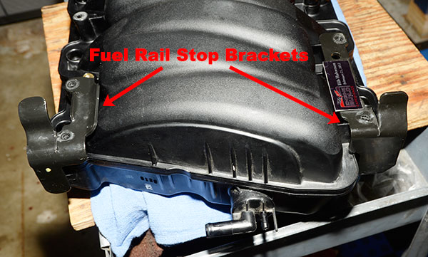
CAC: Because the instructions for the LS7 manifold were written by someone who did not install the manifold on a Corvette, I had a couple of questions about installation issues and one has to do with the fuel rail stops which are part of the car’s crashworthiness and cannot be used with the AAF manifold for the LS7. Why did MSD make a manifold which does not accommodate them?
RS: I can’t comment on that other than to say it might be a question for Caleb.
 CAC: Actually, Caleb wouldn’t comment and threw that question over to you.
RS: I still will pass on the question.
CAC: Obviously the LS7 manifold has been very successful. How many have you shipped?
RS: I can’t share that.
CAC: Has the response so far been what you expected or better than expected?
RE: The sales have been better than expected. Especially the big engine builders like Mast, Lingenfelter, Texas Speed…they’re liking them a lot.
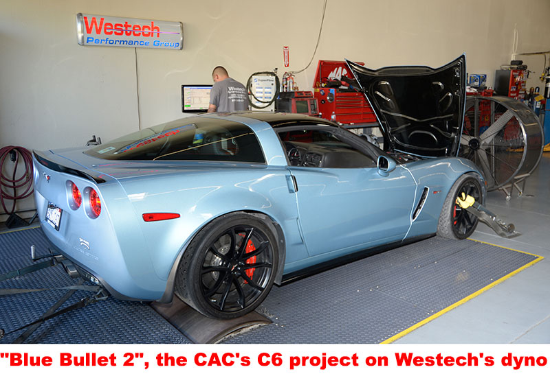
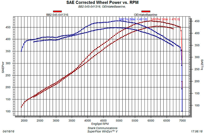
 Using our 2012 Z06 test project, which has a stock engine slightly modified with a production 2011 exhaust system, MSD coils, MSD plug wires and colder Denso Iridium Power IT-24 spark plugs, first, we went to the Westech Performance Group in Mira Loma, California to run the car on a chassis dyno and get a “baseline”. On Westech’s Superflow WinDyn, with the stock intake manifold and stock air filter assembly installed, the car made 453.7-horsepower at 6200-rpm and 423-lbs.ft torque at 4900-rpm, at the rear wheels, SAE-corrected, or about 533-hp SAE at the flywheel.
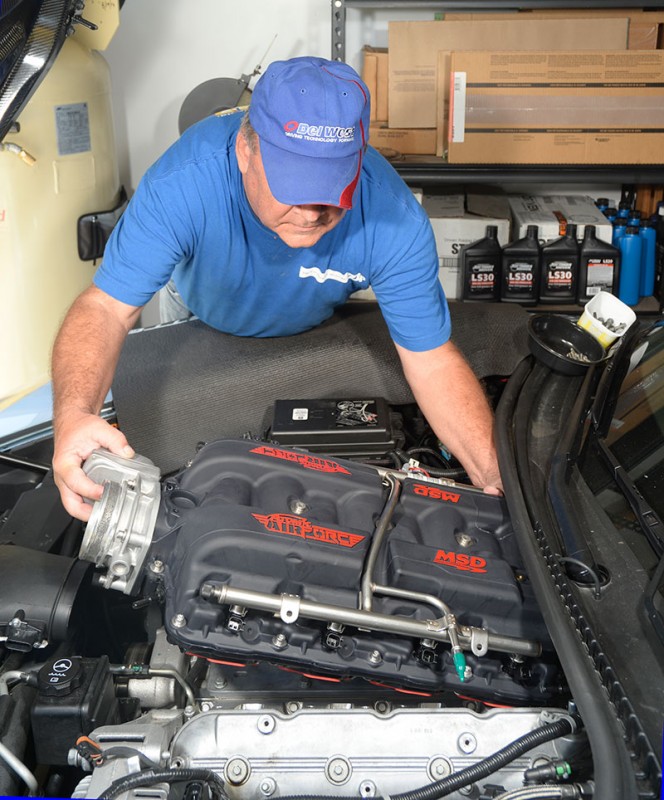
Next, we installed an Atomic Air Force LS7 intake manifold. The installation of the AAF for LS7s is reasonably straight forward, however, there are a few “issues”. One problem is that the installation instructions for a part primarily used on C6 Corvette Z06es were not created during a manifold installation on a Corvette. There is no addendum to the instructions to explain to a Corvette installer the additional steps needed to make the intake functional on an LS7 in a Z06. There there are several installation challenges specific to Corvettes which were unknown to people at MSD who created the instructions and, as a result, are not covered. It’s up to the installer to solve some of these problems.
The first problem is that the size and shape of the AAF manifold precludes reinstallation of the Corvette’s fuel rail stop brackets. These brackets contribute to the car’s crashworthiness by limiting rearward movement of the fuel rail during a frontal impact. It is possible that there is a slightly increased element of risk in removal of these brackets if the car is involved in a significant frontal collision. Secondly, the position of the fuel rail is higher on the AAF manifold. As a result, the stock fuel rail ground strap can no longer be used, but, as it is not necessary in an Atomic Air Force installation, it can be discarded.


The next problem an LS7 AAF installer will have is replumbing the PCV tubing which runs from the oil tank to the rocker covers. There is a tee at the right rear of the stock intake manifold. A second tube runs from that tee, over the top of the stock manifold and then to the rear of the driver side rocker cover. You have to cut the tube off the tee and add a section of hose running from the tee to the remainder of the tube going to the driver side rocker cover. We ended up cutting the tube shorter then, because the AAF manifold’s height, using that extra hose and some clamps to run the tube behind, rather than over top of the manifold. The PCV tube which runs to the passenger side rocker cover, also, needs to be slightly rerouted.
Finally, the PCV connection between the front of the manifold and the valley cover has to be modified to accommodate the 45° angle of the manifold connection on the AAF vs. the 90° connection angle on the stock manifold. If this is not done, that hose will be restricted at the sharp bend causing failure of the PCV system and engine durability problems. The fix is simple: reposition the hose farther out on the valley cover connection which makes the angle of that hose not as sharp and the bend not as tight.


Best results from an Atomic Air Force installation come if the engine controls calibration is changed to better match the manifold’s effect on the engine’s volumetric efficiency. At minimum, both the calibration’s VE table and its intake manifold volume value must be changed. Additionally, the MAF conversion table may also need to be tweaked. The tuning software which must be used for this is EFI Live because its the only calibration editing application which currently supports the intake manifold volume parameter and, because of the AAF’s significantly greater plenum volume, we recommend that be changed. We had the CAC’s in-house calibrator do the work but any “tuner” with LS7 experience and EFI Live can likely do it. This type of calibration work requires a wideband oxygen sensor be installed on the engine and the CAC uses an Innovate Motorsports LC-2 WBO2S.
So, we’re down to the nitty-gritty: a second chassis dyno test at Westech. With the MSD Atomic Air Force intake manifold installed and a revised engine controls calibration programmed into the ECM, but everything else the same; the car made 476.0 horsepower at the rear wheels, SAE-corrected, at 6000 rpm and 451.0 lbs/ft torque at 5000-rpm. That is a 22.3-hp SAE at-the-wheels increase compared to the baseline test. In addition to 22.3 at the wheels for a peak increase, the AAF offered an increase torque from the mid-range on up with the increase at peak torque being 28-lbs/ft. Using the 15% driveline loss rule-of-thumb, the LS7 in our car is now making 560-hp. All power and torque numbers are SAE-corrected.
 That much of an increase from just a change of the manifold was impressive. That said, we think there might be more torque available with additional cal work along and a change to one of Zip Products’ “Mamba” air filter assemblies.
 For more information on the MSD Atomic Air Force intake manifold for the LS7 engine, click here.
For more information on EFI Live, click here.
For more information on the Innovate Motorsports LC-2 Wideband, click here.
