2009 - 2013 Corvette ZR1: GM TechLink: Ceramic Brake Rotors
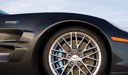
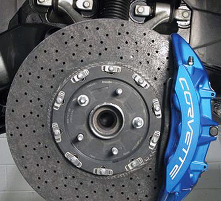
Estimated Reading Time: 4 MinutesThe ZR1 Corvette is equipped with ceramic brake rotors (fig. 4 and 5) , which offer a number of benefits over cast iron rotors:
- No fading
- Wet effectiveness
- No thermal deflection
- Consistent pedal travel
- No corrosion
- Increased rotor life
- No thermal cracks
- Reduction of mass
These brake rotors must be discarded when their mass (weight) drops below the acceptable minimum. Accurate measurement of the brake rotor mass is required to ensure safe operation and braking system performance.
IMPORTANT: The ceramic rotor cannot be machined.
The ZR1 ceramic brake rotors should be visually checked for damage and measured as well as weighed at every pad replacement. They should also be inspected any time potentially damaging materials or road hazards are encountered.
Tire cleaners and dressings should not be allowed to contact the rotors. Only soap and water or alcohol should be used for cleaning the rotors. Loose material can be removed with a stiff brush. The cross-drilled holes can be cleared by hand with a pin or drill bit that is no larger than 5 millimeters in diameter. Be careful to avoid chipping or damaging the rotor surface.
ROTOR PROTECTORS
Foam rotor covers (fig. 6) are included with each car to protect rotors during various service procedures. Dealers should acquire a set of their own for use when servicing the ZR1.
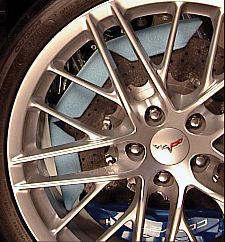
To prevent damage to the ceramic rotor, install a foam rotor protector before removing any wheel. Protectors can be installed through the spokes of the wheel.
IMPORTANT: Disc brake rotor protectors MUST be installed before tire and wheel assembly removal to avoid ceramic brake rotor damage due to contact between the tire and wheel assembly and the rotor. If the ceramic brake rotor is damaged, replacement may be required.
CHECKING ROTOR MASS
The rotors must be weighed before every pad replacement to confirm that the rotor mass is above the minimum (discard) weight embossed on the rotor. The rotor must be replaced if the mass is below the minimum weight.
TIP: The minimum mass is unique for each rotor.
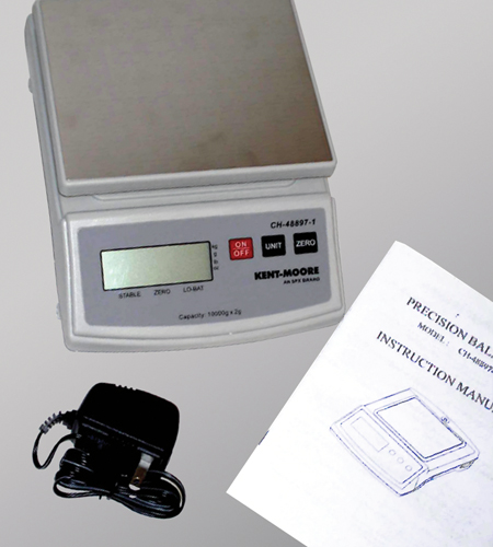
Special tool CH-48897 (fig. 7) is a scale that accurately measures the mass of the brake rotor to determine its suitability for re-use. Before each measurement cycle, use the supplied calibrated weight to calibrate the scale.
There are 10 millimeter threaded holes in the rotor. If necessary, use bolts to slowly push the rotor off of the hub.
NEVER pry or use a hammer to remove the rotor.
Before weighing, remove loose material from the rotor and clear the cross drilled holes.
DO NOT use any liquids to clean the rotors before weighing. The rotors may absorb some
of the liquid, which could lead to inaccurate measurements.
INSPECTING ROTORS
Measurement -- In addition to weighing the rotors, they should also be measured. The minimum thickness must be measured in the swept area of the rotor. The minimum thickness is stamped on the rotor hub.
Chips -- The rotor must be inspected for damage. Measure chips along the rotor edge against the following criteria:
|
Maximum width/depth permitted |
1mm |
|
Maximum length permitted |
10mm |
|
Maximum quantity of damages permitted |
3 |
Grooves -- If at any time the rotor has contacted the backing plate due to excessively worn pads, the rotor should be replaced.
BRAKE PADS
Brake pad inspection is required whenever tires are replaced. Replace pads when they are worn to 2 millimeters of remaining material. New brake pads are 10 millimeters thick.
The ZR1 has an electronic pad wear sensor system. When the pads are worn enough to activate a sensor, a CHANGE BRAKE PADS message is displayed on the Driver Information Center. Replacement sensors are included with new pads.
When replacing ZR1 brake pads, be sure to use brake pad spreaders to compress the caliper pistons into their bores. Using screwdrivers or other tools to compress the pistons can damage the ceramic rotors.
BRAKE BURNISHING
Ceramic rotors are more sensitive to the need for burnishing (bedding) the pads than cast iron rotors. Insufficient burnishing may result in reduced performance and reduced pad and disc life.
SPECIFICATIONS
|
Rotor discard weight |
Discard weight indicated on rotor* |
|
Rotor discard thickness |
Front 35.5mm |
|
Rear 33.5mm |
|
|
Rotor maximum allowable assembled lateral runout |
Front 0.80mm |
|
Rear 0.80mm |
|
|
Rotor maximum allowable scoring |
Front 0.00mm |
|
Rear 0.00mm |
|
|
Rotor maximum allowable thickness variation |
Front 0.20mm |
|
Rear 0.20mm |
|
|
Rotor thickness, new |
Front 36mm |
|
Rear 34mm |
* Each brake rotor is marked with a unique discard weight. This weight is indicated on the carrier section of the rotor and can vary for each rotor in an axle set.
- Thanks to Brad Thacher, Kiley Stites and Kevin Willcock
November 2008 - GM TechLink