1997 - 2002 Corvette: Service Bulletin: SMU - Revised Side Cover and Gasket Replacement (RH)/Differential Carrier Cover and Seal Replacement
Estimated Reading Time: 4 Minutes Source: Chevrolet Dealer Service Bulletin
Number: 02-04-20-003
Date: 07-18-2002
Subject: SMU - Revised Side Cover and Gasket Replacement (RH)/Differential Carrier Cover and Seal Replacement - Right
Model Year: 1997-2002 Chevrolet Corvette
This bulletin is being issued to revise the Side Cover and Gasket Replacement (RH)/Differential Carrier Cover and Seal Replacement - Right procedure in the Rear Drive Axle sub-section of the Service Manual. Please replace the current information in the Service Manual with the following information.
The following information has been updated within SI2000. If you are using a paper version of this Service Manual, please make a reference to this bulletin on the affected page.
Tools Required
- J 36797 Output Shaft Seal Installer
- J 42168-16 Spacers
- J 42170 Bearing and Race Installer
- J 42194 Bearing and Race Remover
Removal Procedure

- Raise and support the vehicle. Refer to Lifting and Jacking the Vehicle in General Information.
- Remove the RH rear tire and wheel assembly. Refer to Tire and Wheel Removal and Installation in Tires and Wheels.
- Remove the RH wheel drive shaft. Refer to Wheel Drive Shaft Replacement in Wheel Drive Shafts.
- Remove the RH muffler assembly. Refer to Muffler Replacement in Engine Exhaust.
- Drain the fluid from the differential. Refer to Lubricant Change.
- Clean any dirt or debris from around the differential cover (right).
- Remove the bolts retaining the differential cover (right).
- Remove the transmission vent tube retainer (automatic transmission).
- Remove the differential cover (right) from the differential.
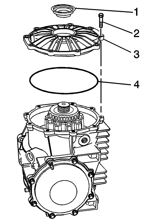
- Remove and discard the axle seal (1), and O-ring seal (4) from the differential cover (right).
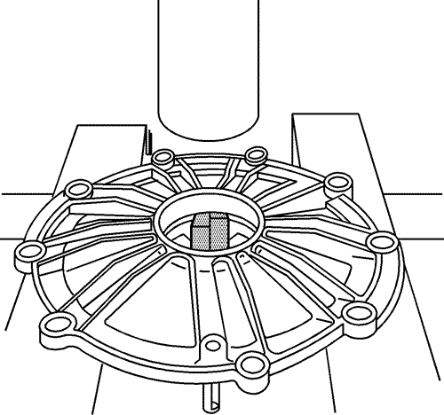
- Install the J 42194 into the differential cover (right), in order to remove the bearing race and shims. Position the cover into a hydraulic press.

- Using a hydraulic press, remove the bearing race (1) and shims (2). Mark or tag the shims for assembly.
Important
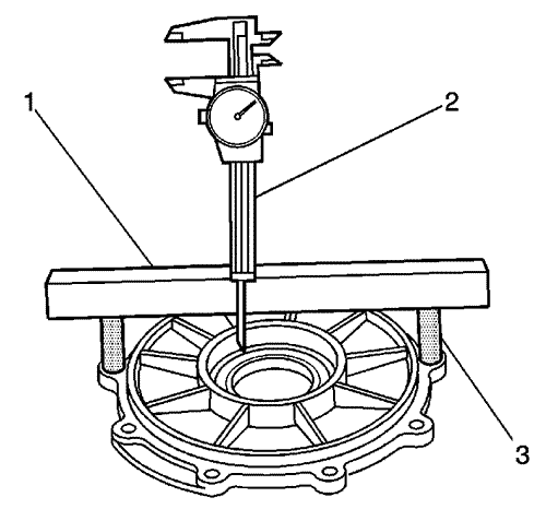
Whenever service requires the replacement of the right side differential cover, the covers MUST be measured and the right side shim pack adjusted to compensate for machining tolerances between the two components. Failure to perform this measurement procedure may result in improper differential bearing preload.
- Use a caliper (2), a straight edge (1), and J 42168-16 (3) in order to measure the NEW differential cover bore dimension. Record the measurement as value A.
- Use a caliper (2), a straight edge (1), and J 42168-16 (3) in order to measure the old differential cover bore dimension. Record the measurement as value B.
- Subtract value B from value A. If the computation is a positive value, add shims equal to the value, to the existing shim pack. If the computation is a negative value, subtract shims equal to the value, from the existing shim pack.
Installation Procedure

- Install the selected shims (2) and the bearing race (1) to the NEW cover (right).
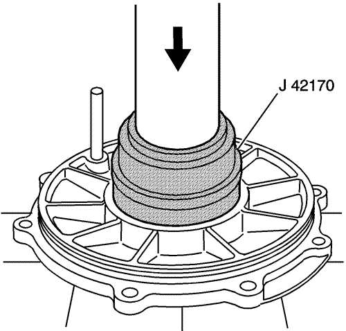
- Press the shims and bearing race into the NEW cover (right) using the J 42170 and a hydraulic press.
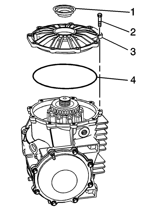
- Clean the O-ring sealing surface on the differential cover (right) and the differential housing.
- Install a new O-ring seal (4) to the differential cover (right).

- Install the differential cover (right) to the differential.
Notice
Refer to Fastener Notice in Cautions and Notices.
- Install the differential cover (right) retaining bolts. Tighten
Tighten the differential cover (right) retaining bolts to 25 N·m (18 lb ft).
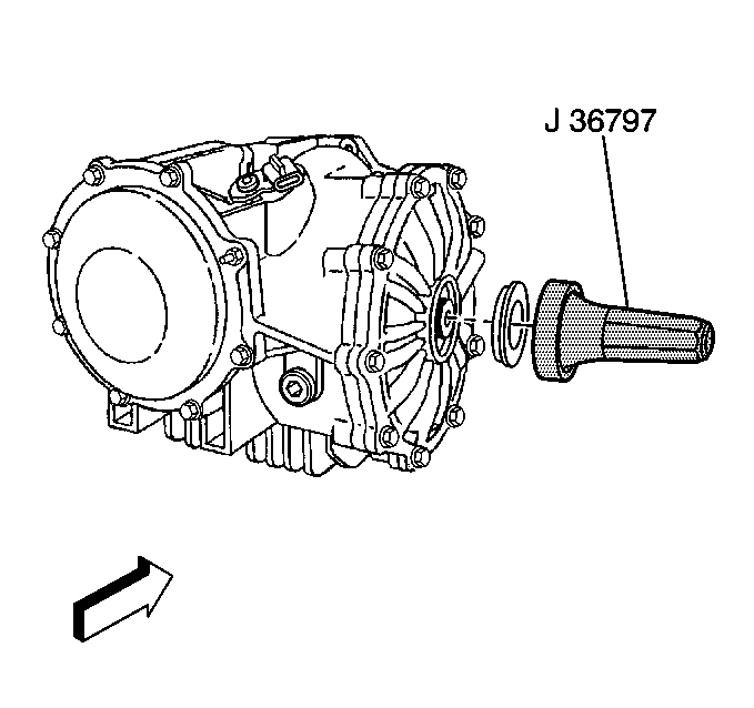
- Install the axle seal into the differential cover (right) using J 36797.
- Install the transmission vent tube retainer onto the vent tube, then position the retainer to receive the retaining bolt (automatic transmission).
- Fill the rear axle differential with the proper fluid and to the proper level. Refer to Lubricant Change.
- Install the RH muffler assembly. Refer to Muffler Replacement in Engine Exhaust.
- Install the RH wheel drive shaft. Refer to Wheel Drive Shaft Replacement in Wheel Drive Shafts.
- Install the RH rear tire and wheel assembly. Refer to Tire and Wheel Removal and Installation in Tires and Wheels.
- Lower the vehicle.
GM bulletins are intended for use by professional technicians, NOT a "do-it-yourselfer". They are written to inform these technicians of conditions that may occur on some vehicles, or to provide information that could assist in the proper service of a vehicle. Properly trained technicians have the equipment, tools, safety instructions, and know-how to do a job properly and safely. If a condition is described, DO NOT assume that the bulletin applies to your vehicle, or that your vehicle will have that condition. See your GM dealer for information on whether your vehicle may benefit from the information.