1984 - 1987 Corvette: Technical Article: Rebuilding the Doug Nash 4+3 Overdrive Unit
Estimated Reading Time: 9 MinutesNash Thrash
Rebuilding the Doug Nash 4+3 Overdrive Unit.
1984-88 manual shift Corvettes came through with the Doug Nash 4+3 overdrive transmission. The ’84 and ’85 units were almost identical, with the only difference being a slightly revised oil pump to reduce some of the whining noise. The ’86-’88 trannys also are very similar to the early units with the major difference being lack of a TV (throttle valve) adjustment.
The 4+3 picked up a bad rep due to failures of the overdrive unit. The main part of the transmission itself has proved to be reliable from the beginning. The overdrive unit is essentially a very small automatic transmission (Powerglide) incorporated into the standard 4-speed. As such, it requires the same kind of maintenance as does an auto trans, such as changing the fluid and screen every 30,00 miles.
The problem with the overdrive unit occurred primarily in the ’84 and ’85 model year units – specifically failure of the annular bearing and thrust washer. These two components were responsible for about 90% of all the overdrive failures. GM corrected the problem by coming out with a new thrust washer about halfway through 1985, and a revised annular bearing at the beginning of 1986. These new components have superseded the old part numbers.
The reliability of the ’86 and later overdrives has been pretty good. Failures here have been traced to downright abuse or undetected leaks which could burn out the clutches.
Overhauling these overdrive units seems to be a mystery – even at some dealerships, as GM no longer provides training on these units. Some special GM service tools are required for the job. There may be ways of getting around these tools, but they do make a big difference in having the job go smoothly, and we strongly recommend their use.
We’ve geared this article to go along with the Chevrolet service manual, as it clarifies the steps outlined in the manual. You’ll also need all the torque specs listed in the manual.

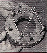
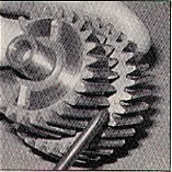
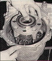
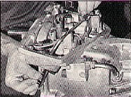
- Remove the 3-1/8 inch pipe plugs from the rear of the overdrive unit. Install the 3 direct pressure plate retaining bolts (Part No. J-34681). Turn the bolts until they’re flush with the case and then screw in two additional turns by rotating each bolt one turn at a time.
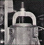
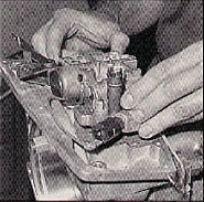
 With the direct piston secured, you can safely remove the front adapter plate. Take care not to pry between the case and the adapter plate or you could damage the sealing surfaces. Continue to disassemble and clean the rest of the O/D unit. To safely remove the direct pressure plate you must use tools J-21420-2 and J-23327 to compress the piston so the retaining bolts can be removed and the spring tension can be slowly released. Inspect all clutches, plates, bearings and races. Replace all damaged and burn components. Measure the original steel plates in order to replace them with the correct size.
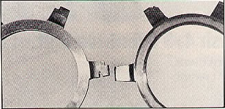
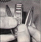
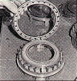
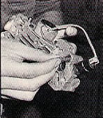
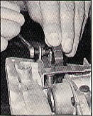
- The old-style direct thrust washer (above right) was replaced in mid ’85-early ’86 with the revised washer on the left. Note the special locking tabs on the fingers that keep the washer secured to the direct piston. The problem with the old-style washer was that it would rotate from side to side and notch into the side of the case and prevent the piston from applying or releasing all the way, causing premature overdrive clutch failure.
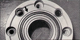
- The annular bearing was revised in 1986 and was improved to withstand side loading on the bearing. Note the "Thrust Here" (arrow) stamped on the outer race. The early bearing was prone to failure and made a growling noise in direct drive but not overdrive. If your unit has an early direct thrust washer or annular bearing replace them with the newer versions.
 Reassemble the overdrive unit by reinstalling direct apply springs evenly around the case. The factory calibrated the pressure at 1,200 psi, so not all the springs are double. Try to balance the spring locations as evenly as possible. Install the direct apply piston making sure the springs line up properly in the cups at the bottom. Use tools J-21420 and J-23327 to compress the springs and re-install retaining bolts J-34681.
 Assemble the output shaft and install the direct clutch sprag. If you remove the side washer on the sprag, you’ll notice a shoulder on one side of the sprag. Make sure this shoulder is on the output side of the shaft when installing the sprag on the shaft.
 Install the direct clutch hub, then a hub thrust washer, then a hub thrust bearing and another hub thrust washer.
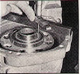
- Install the pump housing and oil drive pin. Install the pump and pump cover. Start all four cover attaching screws, but before lightening, rotate the pump on the shaft a few times, then tighten the screws. This helps center the pump on the shaft. Now install two new O-Rings on the pump cover and the speedo drive gear.
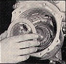
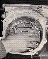
 (right) Lower the output assembly into the case lining up the oil pump ports and bolt holes. Start all four pump attaching bolts, but don’t tighten them yet. First install the driveshaft yoke into the rear of the O/D unit and then tighten the bolts. This will properly line up the pump and shaft in the case.
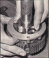
 Install the direct thrust washer, installing the locking tabs into the direct apply piston. Install the thrust bearing, then the thrust washer plate which si identified from the rest of the direct plates by the tooth missing from the outer edge and a notch on a tooth on the circular ground side of the washer. This side goes down on the thrust bearing.
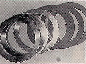
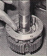
- Alternate the remaining clutch discs and plates until all the plates and discs are installed.
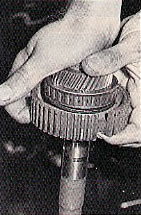
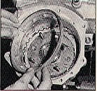
- Assemble the direct clutch drum, thrust plate and bolts. Once all the bolts are installed all the way, secure them in place with a rubber band and lower the drum onto the direct clutches and plates, rotating it back and forth until it seats home. Remove the rubber band.
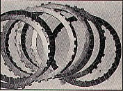
- Install the overdrive clutch pressure plate (the thickest of the overdrive plates) making sure the outside teeth interlock inside of the teeth of the case. Alternately, install the remaining clutches and plates, and install the fingered pressure plate.
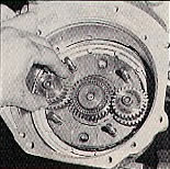
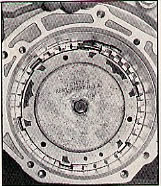
- Install and time the pinion gears. Each gear bears a timing mark. Install the first two pinion gears opposite each other and with the mark to the center. The next two pinion gears are installed with their mark 90 degrees off center – one up, the other down. Install the output shaft thrust washer onto the bottom of the sun gear.
 Install the assembly onto the output shaft. If the sun gear does not go on the shaft easily, the pinion gears may not be timed properly. Rotate the gears until the sun gear will slide on the shaft easily. It may take several tries to get it just right. Install the sun selective thrust washer onto the sun gear with the oil groove down. Next, install the sun thrust bearing.
 Take the annular bearing assembly, turn it over and install the pinion thrust washer and sun thrust washer.
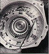
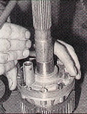
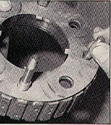
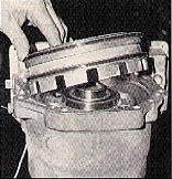
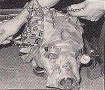
 (right) Lower the assembly onto the direct drum bolts. The assembly should go on easily if the gears are timed correctly. Install 4 new retaining nuts and torque to specs. Check for lash in all 4 pinion gears, which indicates they are correctly timed.
 To measure the correct end play, place the straightedge tool J-34673 across the face of the overdrive unit and use the depth micrometer J-34672 and measure the distance form the top of the bar and the side of the inner face of the annual bearing. Next, measure the thickness of the straightedge with a 0-1" micrometer and subtract this measurement from the reading of the depth gauge. Record this annular bearing depth.
- (above left) Lay the straightedge over the rear side of the front adapter plate. Use the depth micrometer to measure the distance from the top of the bar to the adapter plate mating surface and record the reading.
- (above right) Measure the distance between the top of the bar to the annular bearing seat surface and record this reading.
- Subtract the reading from the top of the bar to the bearing seal from the reading of the top of the bar to the adapter mating surface and record this adapter plate depth. Next, subtract the adapter plate depth from the annual bearing depth to give you your actual end play measurement. The spec for end play is +/- .003" and is adjusted with two selective sun gear thrust washers.
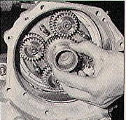
- Install the accumulator cushion piston onto the accumulator piston and install assembly into case. Reinstall large snap ring in case making sure oil feed hold in lower right side of case is not blocked by the snap ring. Place seal protector J-34621 on input sun gear, install adapter plate sun gear seal with tool J-3423 and adapter plate O-ring, then install the adapter plate. Apply a light coating of RTV sealant on the adapter plate bolts and tighten to specifications.
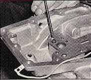
- Reassemble the valve body and install a check ball into the case.
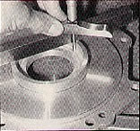
- Install a new gasket on both sides of the separator plate and position on case.
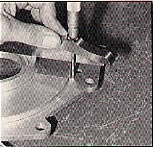
 (right) Install second check ball on separator plate.
 (right) Install check ball spring in valve body and retain with petroleum jelly.
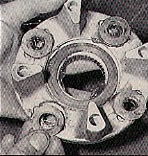
- (above left & right) Install the valve body on the case. Two allen head bolts are used in retaining the valve body. The one with the machined outside head drops down a hole and is secured.
 To adjust the TV cable on the valve body, install tool J-34671-1 into the TV cable bore on the side of the case and set the hook on the high step of the gauge. Place the cam stop on the valve body as close to the lever as possible and install the retaining bolt.
- Next, set the hook on the lower step of the gauge. Place tool J-34671-2 between the piston and solenoid bracket. Adjust the bolt on the TV lever until the lever just touches the tool.
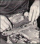
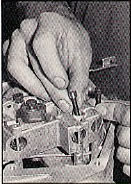
 To measure the clutch pack clearance, remove the first 1/8" pipe plug from the left side of the 0/D unit. Install air line fitting J-34742 into pulg hole and tighten (remove shrader valve from fitting). Loosen the 3 pressure plate retaining bolts evenly until spring pressure is released. Assemble J-8001 dial indicator to the rear of the O/D unit in order to measure the movement of one of the pressure plate retaining bolts and zero gauge. Use allen key to keep check ball seated in valve body. Apply a minimum of 100 psi to air line fitting and read dial indicator. If reading does not fall within specs (.050-.070") it will be necessary to disassemble the O/D unit to change the direct clutch selective clutch plates. If readings are within specs, remove retaining bolts and air line adapter. Coat the 1/8" pipe plugs with anti-seize compound and install plugs.
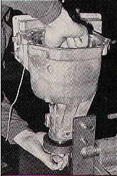
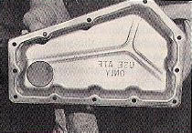 Install oil filter on pickup tube. Install magnet in oil pan. Apply a bead of RTV sealant to the oil pan flange and assemble wet. Install pan bolts and torque to specifications.
|
David, great write-up. Was wondering if you know or recommend a place that sells the pressure switch and overdrive solenoid for the 4 3? Thanks, George