1959 Corvette: Service News: Fuel Injection Pump Leakage
Estimated Reading Time: 2 Minutes Subject: Fuel Injection Pump Leakage
Model and Year: 1959 Corvette
Source: Chevrolet Service News
Date: March 1959 - Volume 31 - Number 3
Gasoline leakage observed at rear of the fuel injection fuel meter may result form a worn drive shaft seal on the high pressure fuel pump. The pump mounts on the rear face of the meter housing.
A replacement fuel pump drive shaft seal is available, through Chevrolet Parts channels, in Kit No. 7017174 (kit also includes the pump drive shaft and necessary pump mounting gaskets).
NOTE: Pump drive shaft should be replaced when a new seal is installed, thereby preventing minute scratches on the old shaft from contributing to early seal failure.

- Remove high pressure fuel pump from fuel meter.
- Mark relationship of pump body, gear housing, and front cover.
- Remove four Allen head screws and remove front cover.
- Using china marking pencil, mark relationship of idler gear to drive gear.
- Remove gear housing and idler gear.
- Remove drive gear by extending shaft beyond gear so that drive pin may be removed.
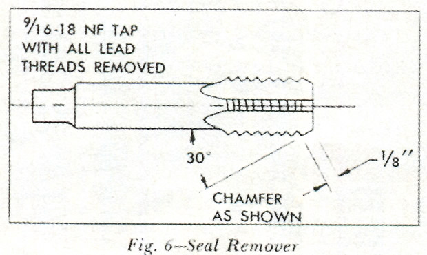
- Screw reworked tap (Fig. 6) into seal.
CAUTION: Tap must be seated in seal in no more than 2 or 3 turns or damage to the rear busing will occur. - Drive seal and tap out of pump housing using old drive shaft inserted from bearing end.
- Slide drive shaft through the pump body and remove through seal end to avoid the possibility of burrs scratching the bushing.
- Place a new seal in position in pump body with open end of seal downward. To satisfactorily replace the seal, it will be necessary to first make a seal remover (Fig. 6) and seal installer (Fig. 7), then perform the replacement exactly as described in the following.

- Press into place using seal installer tool (Fig. 7).
- Lubricate new drive shaft and install into pump housing from seal end.
- Install drive gear, idler gear, and gear housing in their original relative positions and remove china markings.
- Assemble front cover and install screws finger tight. At the same time, rotate drive shaft counterclockwise (looking into the drive cable end). If the shaft turns freely, the gear housing is properly centered.
- Tighten two of the Allen head screws diagonally across the front cover. If the shaft turns freely, tighten the remaining two and recheck the shaft for free rotation.
- If the pump does not bind, tighten the four attaching screws to 40 inch-pounds.
- If at any time the pump tends to turn hard, loosen the four Allen head screws, reposition the gear housing, and repeat steps 14, 15 and 16.