C6 Corvette Z06: The Heads On Test - How to Perform Low-Accuracy Measurement of LS7 Valve Stem to Guide Clearance - Page 4 of 4
by Hib Halverson
© December 2014
No use without permission, All Rights Reserved
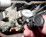
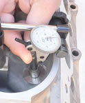
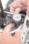
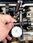
Positioning the test indicator requires a little more care because, unlike a dial indicator, which may have as much as an inch of measurement range, test indicators have far less and most can only measure half their total range. For example, the Fowler X-Test used for this story has a total range of .030-in., but it can only measure .015-in. in either direction. Consequently, when using a test indicator, you must position it such that all wiggle test movement is between zero and .030-in in the direction of travel. What do you do if your clearance measurement exceeds the test indicator's travel? Get new heads.
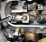
The other positioning issue to consider when using a test indicator is that the indicator's contact point must touch the valve stem just above the top of the guide at a 12° angle to the valve stem. Once the test indicator is set-up, the wiggling part is the same as discussed in the dial-indicator section above.
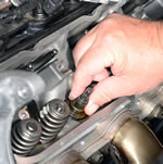
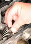
Once you are done with #1 cylinder, remove the measuring hardware. Reinstall the two valve seals with the black one on the intake valve and the brown one on the exhaust valve. Pull the valves up so they seat and re-apply the air pressure. Set the springs back in place. Deploy your spring compressor and, while the springs are compressed, drop the retainers in place and reinstall the locks with their taper pointing towards the engine. Finally, drop the lash cap onto the tip of the intake valve stem. Release the air pressure and, finally, reinstall the alternator.
Now, move to the next cylinder in the firing order, #8. The next two cylinders, #8 and #7 are the toughest to wiggle test because #8 is too close to the firewall and the power brake booster is in the way when doing #7. Once you get past 8 and 7, the rest of the cylinders in the firing order, 2, 6, 5, 4 and 3, are easier to test, plus—after doing the first three, you'll be an expert. The last five are all done the same way except that you may need to reconfigure your dial or test indicator set-up depending on where the nearest rocker arm mount hole is located in relation to the valve you are testing or you may need to reconfigure it to get to the proper spot on the valve stem.
Once you have your measurements, rotate the engine back to #1 and reinstall the first eight rocker arms, per the Service Manual. Then roll the engine over to #6 and install the second eight rockers. Add the rocker covers, reconnect the PCV pipes and reinstall the ignition hardware.
If you used a test indicator, you're work is done and you can skip down to the last two paragraphs of this article. If you measured at the top of the valve stem with a dial indicator, now, you need to correct the wiggle measurements for the offset measuring location. To do that, you solve a couple of right triangles with trigonometry. Most of us hated high school trig. Fortunately, the internet comes to our rescue in the form of a number of java script web pages which solve triangles and are easily found in a web search. On one of these pages, for the first calculation, you enter 90° for the right angle, your raw wiggle measurement for the base and the length number you recorded earlier for the adjacent side. The number the first solution supplies is re-entered as angle A in a second solution. The 90° is entered again and you now enter 1.0-in (half the length of the guide) for the adjacent side. The result is the new base side length, which was, with our LS7's #1 intake valve, .00287-in. or, rounding to four places, .0029-in.
For those who's interest in trig and triangle solving web pages rivals that of watching grass grow, the correction for use of a dial indicator contacting at the top of the valve, requires you multiply all the raw wiggle test measurements by 0.41, however, that factor is only accurate if the distance from the dial indicator pintle to the top of the guide is 1.44-in. and the guides are the 2.0-in. OE length. That factor will result in reasonably close conversion if the distance between the indicator pintle to the top of the guide is between 1.4 and 1.5 inches. If the guides are a non OE length, that factor will be inaccurate. If the distance between the indicator pintle os other than 1.44 or the guides are a non OE length, that factor will be inaccurate. Our advice is, if you want a precise measurement using a dial indicator and the distance between your pintle and the top of the guide is other than 1.44-in., that you use one of the triangle solution java script web pages and not use our 0.41 conversion factor.
GM's production stem-to-guide clearance tolerance is 001-.0024-in. for intake valves and .001-.0026 for exhaust valves. The the maximum acceptable clearance for either valve is .0037-in. Anything over that requires removal of the heads for repair or replacement.
If you are a DIY wiggle tester and the engine is under warranty, we suggest you whip out your iPhone and take a couple of digital images or video of indicator readings, your measuring set-up and the VIN plate at the base of the windshield then put everything back together, take the car to the dealer and tell them you want the heads warrantied due to guide wear.
We recommend "wiggle testing" any LS7 which has more than 10,000 miles on it.
One question we've received several times since the original version of this article was posted is: "Where should I send my out-of-warranty heads to be repaired?" The answer to that question is two-fold. If you simply want the heads repaired but not modified, a skilled and experienced automotive machine shop which has a Serdi valve seat machine will likely be able to replace the valve guides with manganese bronze guides then recut the valve seats to establish concentricity. An example of such a business is Mark DeGroff's Cylinder Head Service in Northridge, California which was discussed in the LS7 article which linked to this story.
If you want the heads not only repaired, but you want them ported and fitted with premium components, such as better valves and higher tension valve springs, there are several cylinder head service facilities around the U.S. which specialize in the LS7 head. Below is an alphabetical list of head service vendors which the Author has either toured personally or is staffed/operated by people the Author interviewed in the process of preparing the CAC's series of LS7 articles. We are confident that all these businesses are capable of premium-quality LS7 head work. The first two are "complete service" facilities in that they not only do head work but they work on vehicles so they can perform all the removal/replacement labor. The second two are strictly cylinder head services and do not work on vehicles.
Head Service Vendors:
Katech, inc.
Lingenfelter Performance Engineering
Texas Speed and Performance
West Coast Cylinder Heads
Tool Source list:
- Crane Cams
- Fowler High Precision
- Goodson Shop Supplies
- Lingenfelter Performance Engineering
- Summit Racing
