C6 Corvette Z06: The Heads On Test - How to Perform Low-Accuracy Measurement of LS7 Valve Stem to Guide Clearance - Page 3 of 4
by Hib Halverson
© December 2014
No use without permission, All Rights Reserved
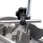
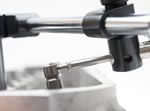
The vertical support beam of many foreign-made indicator bases has the same, M8x1.25 thread as an LS7 rocker arm bolt, so the post can be unscrewed from the base and installed directly onto the cylinder head by threading it into a rocker arm bolt hole. Tighten the vertical beam so it's snug but not tight enough to deform the rocker arm mount, then install the horizontal support beam and, finally your measuring device.
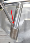
If you're using a dial indicator, the challenge comes in trying to position it to properly measure stem-to-guide clearance as shown by the drawing in the Service Manual. In fact, it's impossible. The manual shows a dial indicator measuring stem-to-guide clearance just above the top of the valve guide. While that is the best place to measure, the LS7 head structure will not allow a dial indicator to be positioned such that accurate measurement is possible because the angle between the indicator spindle and the valve stem is significantly less than 90°.
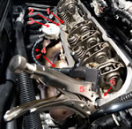
A fundamental concept in metrology is the "Abbe Principle of Alignment". With respect to dial indicators, it mandates that the axis of movement being measured be collinear with the axis of the measuring instrument. If the two axis are not collinear, "cosine error" occurs in the measurement. The farther the two axes are from collinear, the greater that cosine error. Additional error can be introduced into the measurement by a mechanical problem created when the angle at which the dial indicator spindle meets the valve stem is so acute that the square edge of the indicator point and not on the spherical point itself contacts the valve stem. Still more error comes if the indicator binds which can happen when indicator spindles are set-up at acute angles to what's being measured. Yet more error occurs when the indicator is mounted on a base which is flexible. Finally, error can arise when the indicator base is clamped to the cylinder head structure with a "Vise Grip"-oh, and then there's the metal chips which might end up in the oiling system when the Vise Grip hardened steel jaws bite into the soft aluminum head structure.
In a "perfect storm" situation, where all these errors happen and are cumulative, indicated guide clearances can be larger than actual clearances. For example, using the errant indicator set-up we found on the Corvette Forum, we measured the guide clearance of the #6 intake valve on the engine in the CAC's longterm test Z06 a number of times. It was anywhere from .0032" to .004" and the readings did not repeat consistently. For most measurements, we saw .004", but there were others at .0032" and .0037". Conversely, using the "test indicator method," discussed later in this article, we consistently measured .0025" and we know that is accurate because, in researching the CAC's main LS7 article from which this article linked, when the same head was apart, our head service vendor, DeGroff's Cylinder Head Service in Northridge, California, measured that same valve guide with a Sunnen dial bore gauge and it read .0026" clearance.
When using a dial indicator, a stiff mounting and adherence to the Abbe Principle of Alignment are key to accurate measuring of guide clearance. Failure to consider those factors in the dial indicator set-up results in measurement which is 40-60% greater and that may have a you paying for an expensive head repair when it's not needed. For example, if you set-up a dial indicator to wiggle an intake valve, as discussed in the aforementioned Corvette Forum thread, and your reading is .004-outside the service limit of .0037-the actual stem-to-guide clearance is .0025, way under the service limit and close to the production tolerance of .001-.0024. If you used the same indicator set-up on all your valves, they all read .004" and you spent the money to "repair" your heads, you would have flushed that cash down the toilet because your guides were not worn in the first place.
An even more significant problem occurs when such an inaccurate wiggle test is done by service technicians charging money for their work but who either don't care about or are unaware of the correct way to set-up a dial indicator or-perish the thought-out of nefarious greed, are aware of the correct set-up, but who know it can result in greater measurements if they purposely set up the indicator improperly. They show the customer the "readings" and tell the customer his/her valve guides are worn-when they really are not-and that the solution is $3000.00 worth of parts and labor to replace cylinder heads-which were ok to begin with.
Worse yet-what of the case were someone wants a wiggle test done to counter a warranty claim denial by GM for lack of the symptoms outlined the the Information Service Bulletin covered in the CAC's main LS7 article? If you present GM with wiggle test data to back-up your contention that denial of your warranty claim was unjust, you'd better come to the table with accurate data because the first thing GM is going to do is take the heads apart and verify the numbers you give them.
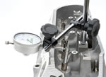
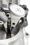
For accurate dial indicator measurements, the indicator spindle should contact the valve stem close to or at a 90° angle. To achieve that, you must position the indicator higher, so its spindle touches the stem just below the valve tip, but not in the lock groove. It should, also, be just above the rocker cover rail. Using a six-inch ruler, measure the distance from the indicator point down to the top of the guide then add one-inch, which is half the length of the guide. Usually this number will be just under 2.5-in, however it may vary if you are using non-OE valve guides. Not all aftermarket guides are 2-in. some are longer. If you are wiggle testing an engine with aftermarket guides, to do the process properly, you need to know the guide length.
Once you have the indicator correctly positioned, move the valve down slightly so it's just off the seat. If the indicator slips off the valve stem, reposition the indicator slightly lower. Gently push the valve stem so that you can zero the indicator. Then pull it the other way and note the reading. Wiggle a couple more times until the measure repeats. Make sure you're wiggling parallel to the dial indicator stem. When you wiggle, take care not to touch the indicator or its mounting. Take your measurement-let's say it's .007-in., the raw measurement for the #1 intake valve in my LS7-and record that number. Now, move your indicator set-up and measure the #1 exhaust valve and record that number.
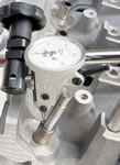
Earlier, we mentioned using a test indicator rather than a dial indicator. The beauty of the test indicator is that it can be positioned in a manner that allows direct and accurate measurement of stem-to-guide clearance right at the top of the guide. The nice thing about measuring there is no computation is necessary to derive the clearance number and there is no error introduced if you inadvertently bend the valve stem. Don't laugh. You'd be surprised how easy it is to bend the valve stem half-a-thousandth of an inch.
