2003 Corvette: Technical Article: Magnetic Ride - Star Wars Meets the 50th Car
Estimated Reading Time: 40 MinutesMagnetic Ride - Star Wars Meets the 50th Car
 |
by Hib Halverson,
©2003 Shark Communications
no use without permission
I hit the last dip at 100 or so, on the brakes, getting ABS as the rear suspension kissed the rebound stops, then back-shifted for a right at the end of the straight.
Suddenly, I thought of Star Wars.
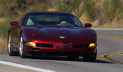
Remember Episode One’s pod race? Anakin Skywalker and some really ugly aliens are racing across a desert on Tatooine. As Anakin skims balls-out, just above the ground, other pods crash in flaming wrecks. He hits turbulence. All kinds of stuff is blowing-up, right, left and underneath. Pod races are tougher than Winston Cup at Bristol.
Though the ride is rough, young Skywalker always has his racer under control. No doubt, his pod has some amazing ride control system which damps the bumps and dips.
 |
|
Click image for larger view
Will this be the Corvette C25 convertible in Pod Racing trim? How those big turbofans will meet pass-by-noise requirements. Pedestrians better watch out when you light the afterburners, too. You can bet this car (...plane, or whatever) will have a Star Wars ride control system. Image: Author |
Back in the 21st Century, at the "Milford Proving Ground", General Motors’ enormous test facility 32 miles northwest of Detroit, there is a section called the "Ride and Handling Loop." It’s a torturous, four-miles of chatter-bumps, dips, pot holes and rail crossings mixed with sharp turns, esses and sweepers. To Mike Neal, Corvette’s ride-and-handling engineer; the "R/H Loop" is, well...a home away from home.
The Loop’s backstretch is half-a-mile of what’s either the worst (if you’re a highway engineer) or the sweetest (if your testing suspensions) bunch of dips one can imagine.
Driving an ’03, 50th Coupe at 100 over this stuff seemed like racing Ani’s pod. Well ok, no open cockpit and no after-burning turbofans out front, but it did have a Star Wars ride control system.
I was on the R/H Loop to learn about Corvette’s latest suspension advancement. Chevy Marketing wizards call it "Magnetic Selective Ride Control" (MSRC). Engineers at General Motors and the Delphi Corporation who developed it, call it "MagneRide" or just "MR".
Mike Neal and I were in a "MR car," making one hundred mile per hour passes across these dips. The car was fully controllable. It wasn’t getting airborne. We weren’t getting bounced severely in our seats.
The meanest of the R/H Loop’s dips is off by itself on the front straight. About eight feet long and 10-inches deep, it’s the only one marked with a sign: "Bad Dip".
 |
 |
|
|
Click image for larger view
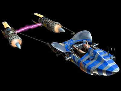
Here we are at the Milford Proving Ground’s infamous "Bad Dip." Mike Neal was at the wheel of a base car. This flight was the result of a 80 mph pass. Image: Author |
Click image for larger view
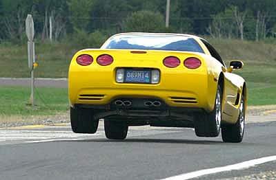
Same dip. Same speed but, this time, Neal is in a 50th Car with MagneRide. Quite a difference! Image: Author |
At 80, Neal and I freaking flew a base C5 over it-"Dukes of Hazard" stuff, probably 18-inches up, airborne for 25 ft and my fat self flung up against the seat belt then smashed down in the seat.
In a MR car at the same speed, the difference was astonishing. We didn’t get air and didn’t bounce around inside the car as much.
 |
|
Click image for larger view
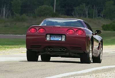
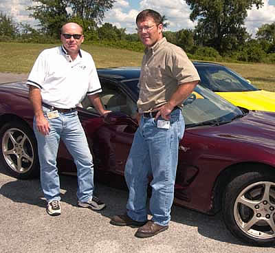
Meet Mike Neal. Since the mid-’90s, he’s been the "guy" for Corvette ride-and-handling. Much of how a C5 feels when you go fast through the twisties comes from this man’s work. Neal seemingly has nerves of steel and lots of life insurance because, when told by crazed journalists they want to do the Bad Dip at Milford at 120 mph, he shrugs then suggests they "...keep it straight." Either that or we writers really don’t go that fast and he’s humoring us. Image: Author |
"Hey Mike, what’s the fastest you’ve gone across that sucker?"
"120, but we uh...weren’t gonna let journalists do that."
"Next time, I’m taking it at 120."
"Ah...ok but stay in the center and hold it straight."How often has Neal seen life flash before him when crazed media guys do this stuff?
I came off the Loop’s west-end sweeper in third, at 100 with my foot flat on the floor. I tagged the LS1’s limiter, got fourth and held 120 across some smaller dips and rough pavement. In the distance I saw the sign and, a split second later, the scrape marks in the pavement.
Whump! Ka-Thunk.
No long flight through the air, though the rear wheels did get off a few inches. We got bounced around, but much less than in the base-car at 80.
I’ve been writing about Corvette suspensions since the early 1980s and I’ve gotta tell you: Magnetic Selective Ride Control is some pretty amazing suspension technology or as Yoda might say, "Very Star Wars, this MR stuff is."
The History of Corvette Electronic Ride Control Systems
A ride-adaptive shock absorber system has been a Corvette option since 1989. "Ride-adaptive" means the shocks adapt their damping to the ride dynamics present as the vehicle moves. Corvette’s ride-adaptive systems have always been computer-controlled with the driver having some input to the strategy the computer uses to set the damping.
 |
|
Click image for larger view
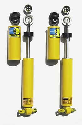
Into the historical archives for this one. This is a set of front shocks from a C4 equipped with SRC. Image: Author |
The first of these systems, "Selective Ride Control" (SRC) was developed by Bilstein for the 1990 ZR-1. As RPO FX3, it was optional from 1989 to ’95 on all C4s but standard on ZR-1s. SRC had a wide range of damping available between its softest and firmest setting. It changed its damping according to vehicle speed. The faster the car went, the stiffer the shocks got.
 |
|
Click image for larger view
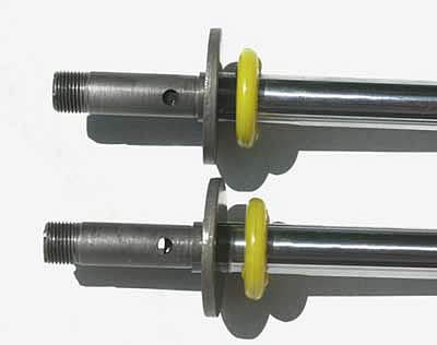
The heart of an SRC shock was a sleeve-valve bypass that allowed shock oil to bypass the valves in the piston during damping. The amount the bypass was open determined the magnitude of the damping. Top shows the valve closed. Bottom shows it open. Image: Author |
While it’s bandwidth was wide, SRC could not adjust damping according to ride movement because its response time was quite slow, about 180 milliseconds (mSec) or about a fifth of a second. In 1992, hardware improvements and software changes cut that in half, but still, by today’s standards, you could have benchmarked SRC’s speed with a sun dial.
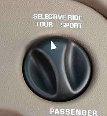
The driver had input to this system via a three-position switch that altered bandwidth and moved the damping range up or down the vehicle speed scale. The "Tour" position had six steps of damping and remained at the system’s least aggressive valving until 50 mph. From there, damping increased in 25 mph increments until 100 mph where the highest step in that range used about 50% of the system’s available damping authority. "Sport" had five ranges of damping but its lowest step (0-25 mph) had the same damping that Tour had at 100 mph. Sport’s highest step used about 80% of the system’s available damping authority. The "Performance" range (marked "Perf" on the switch) only used four steps and its lowest step was more aggressive than the highest step in Tour. The Perf range was also the only one where the system’s full damping authority was used and that came at speeds of above 78 mph.
 |
|
Click image for larger view
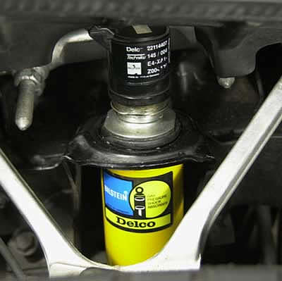
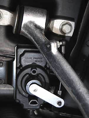
Shown here on a 1995 ZR-1, each SRC shock had an "actuator" on its top that turned the sleeve valve. The amount the actuator turned the valve shaft was determined by a signal generated by the SRC controller in a storage well behind the driver seat. Image: Author |
SRC was leading-edge stuff for a high-volume sports car at the end of the 1980s. The system’s control software was the most sophisticated used in any electronic ride control system of the period. Even at the end of its production in model year 1995 (MY95), it was still a very useful system.
In 1996, for the final C4 model year, RPO F45, "Selective Real-Time Damping" (RTD) was released. Developed for GM by Delphi Corporation, RTD used data from suspension motion sensors to set the damping level. The system’s response was "near real time" To process data and accomplish a damping change inside the shocks took about 35-mSec. RTD marked the first time any production sports car had a shock absorber system which "read" the road and used that data to change damping.
MY96 RTD’s weakness was only two levels of damping: "soft" and "firm". This system was a limited in bandwidth but was "pulled forward", as Dave Hill likes to say, from the C5 development to get a "road-reading" damper system on Corvette and generate some additional technical interest in C4 during its final year.
Some critics of the system, this writer included, believe that, under marketing pressure to get such a system in production, GM compromised on damping bandwidth because the technology necessary to have a wider-bandwidth RTD system was not mature in the precision and speed with which shock adjustments had to be accomplished.
This bi-state system’s lower level of damping provided outstanding ride quality but the upper level ended-up only as aggressive as the system’s limited bandwidth would allow. This amounted to "a little less soft", and more typical of a base C4’s fixed valve shocks, rather than truly "firm" damping appropriate for performance driving. The selector-switch carried over from SRC but it’s functions were different. "Tour" enabled mostly soft damping. "Sport" had damping mostly firm. "Performance" locked the system in firm.
C5 arrived in 1997 with continuously-variable RTD having additional bandwidth through improvements in accuracy and speed of valve adjustment. System response quickened to about 22-mSec. "CVRTD" had a more powerful controller but used the same ride sensors and selector switch. While it was another step forward, those who’ve read my articles about Corvette suspensions in the past know I was not a fan of this system, either, because I felt it did not contributed enough value to the car’s handling.
"MR is a lot quicker than CVRTD," Mike Neal tells the Corvette Action Center, "and that was a fast system by the world standard. Amongst those doin’ electronically-adjustable suspensions, the Delphi CVRTD system was as fast, if not way faster than others and MR is even faster than that."
While I was not a CVRTD supporter, the fact remains that Neal is right. PR guys at European and Asian car companies can spin all they want, but their chassis engineers can only wish they had the ride control Delphi sells to GM in the various RTD systems currently on Cadillacs, some trucks and Corvette up to MY02.
"When we did CVRTD, the easy part," Mile Neal continued, "was damping body motion because it is slow, in the one-to-two hertz range. The hard part was the wheel control stuff: chatter bumps, impacts, in the 12-15Hz range. How do you get from being on a smooth road, where you had low activity and all of a sudden-ka-boom!- you have a big impact?
"Can you bring all the forces to bear quick enough to damp the suspension in a way that isn’t harsh and brings plushness to the feel of the event? That was a big challenge with CVRTD but MR is fast enough to be able to do that."
With SRC and RTD, damping was hydromechanical. Shock oil was forced through small orifices, or "valves," by movement of the shock piston and rod in the oil-filled shock body. The valves’ resistance to oil flow provided the damping. With SRC, a sleeve valve "bypass", concentric with the shock piston rod and adjusted by an electric actuator, provided the change in damping. With RTD, it was a bi-state valve or continuously variable pressure control actuator on the side of the shock.
A traditional shock absorber doesn’t have just one valve. It has many, all with different opening, closing and flow characteristics. Today’s conventional shock absorbers are devilishly complex devices aimed at that elusive damping compromise between performance handing and pleasing ride. While they can do one or the other very well, even the best hydraulic shocks are only adequate in how they address that compromise.
All ride-adaptive systems using adjustable valves have limited bandwidth because of the slowness with which they change states along with the slow response of the other, fixed-orifice valves. Darin Dellinger is a Delphi engineer who’s worked on Corvette ride control systems for a number of years. Emphasizing this slowness, he told us, "One of the challenges we had to overcome with previous hardware related to valving. Damper valving is a hindrance. Valving, in itself, has response time. So there’s slowness just in the way those valves crack open or closed. The MR damper, because it doesn’t have valving, opens up a whole bunch of opportunities we didn’t have before."
 |
|
Click image for larger view
At a briefing in California in the spring of 2001 which introduced the ’02 Z06 to the press, Dave Hill hinted at some C6 technology that would come early to C5. Now we know this was MR. Image: Author |
Eliminating these problems in one fell-swoop is RPO F55, Magnetic Selective Ride Control. Under development by Team Corvette and Delphi since 1996, MR has taken a long time to come to fruition because of the engineering and development challenges in making it perform well. Dave Caldwell, GM’s spokesperson for all things engineering-related on Corvette, told the Action Center, "Dave Hill viewed this (MR) as a ’holy grail’ kind of a thing that people have been trying to do for 20 years or more. We were never sure when it was gonna get in the program, but we knew it would get in when it was ready."
Hill had been hinting since early-’01 about, "...an aspect of C6 technology we are trying to pull ahead into C5." MR was that technology. MagneRide debuted in mid-’02 on the Cadillac STS. The system was altered slightly then put on Corvette for MY03. It is optional on all coupes and convertibles, standard on any car with the 50th Anniversary package but not available in combination with Z51 or on Z06es. For 2004, it will be optional on coupes and convertibles.
After 2003, use of MagneRide on GM vehicles will continue to increase. It will be standard on the ’04 Cadillac XLR and optional on the ’04 Cadillac SLX, a new, medium sized, rear-drive SUV.
MSRC is superior to other variable damping systems because 1) it can apply almost twice the damping force and 2) has a quicker average response time, about 10-mSec. GM claims MR is "five times faster" than RTD. We researched that number and believe it was derived by comparing the slowest expected RTD response (30-mSec.) with the quickest expected MR response. (6-mSec.) In reality, depending on the damping situation, MR’s response time ranges from about "the same as" to "as much as five times quicker than" ’97-’02 RTD but, on average, responds twice as quick.
Star Wars Secret Sauce
 |
|
Click image for larger view
A scanning electron microscope image of carbonyl iron powder similar to that used in the Corvette’s MRF. The sizes vary from about four to about 22 microns. Image: BASF |
There’s no oil in a MR shock. It’s replaced by magnetorheological (say "mag-knee-toe-ree-oh-lodge-i-cal") fluid. "MRF" is manufactured by Lord Corporation of Cary, North Carolina and branded "Rheonetic Fluid".
MRF is a staggeringly complex, synthetic-hydrocarbon-based liquid having somewhere between 20% and 40% (by volume) carbonyl iron particles (CIP) in suspension. CIP are made using the "carbonyl decomposition process", developed by BASF in the 1930s. Iron pentacarbonyl is thermally decomposed, during which particles form and develop a shell structure. The result is microscopic, iron spheres having traces of carbon, oxygen and nitrogen in their shells. During this process, decomposition conditions determine the properties of CIP, including a key factor in MRF: "particle size distribution," which is the various sizes of particles, on a percentage basis, making up a volume of CIP. The particles’ high purity, typically 97.8-99.5% iron, offers excellent electromagnetic properties.
 |
|
Click image for larger view
It takes a complex procedure and a huge manufacturing operation to make CIP suitable for use in MRF. This chart details the chemical and mechanical processes at work during decomposition. Image: BASF |
CIP are a versatile substance. Not only are they a component of MRF, but they are the basis of products as varied as LS1/LS6 connecting rods and the iron "fortifiers" in food and nutritional products. Pour CIP in a mold, sinter, forge, then machine, and you have a Corvette rod. Crush some Total breakfast cereal, then run a magnet through it and you come-up with CIP.
There are few manufacturers of carbonyl iron particles and even fewer make CIP suitable for MRFs. BASF is the only one we could find that sells a product intended for magnetorheological fluids. BASF’s Dr. Al Friederang told us via email that one grade, "...’Carbonyl Iron Powder CR’ is specifically designed to meet the requirements of the magnetorheological fluid technology in automotive applications such as shock absorbers."
Asked for more information about Grade CR, Dr. Friederang was less accommodating, however, the good Doctor hinted that CR was similar to another BASF product, CM. According to BASF’s web site, Grade CM CIP vary in diameter from four to 22 microns with at least 50% of the particle distribution being seven microns in diameter. A micron is one millionth of a meter or 39 millionths of an inch (.000039-in.) so, we’re talking way small particles.
Adding to this frustrating lack of information, Lord Corporation, also, declined to provide specifics about Rheonetic Fluid citing the proprietary nature of the product. It is possible Lord does not use BASF raw materials but, whatever the source of its CIP; we think it’s at least similar to BASF’s grades CR or CM.
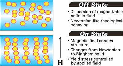
Before the particles are added to the fluid carrier, they look and feel like black flour. Once MRF is formulated, it looks and feels like dirty engine oil. The key property of this Star Wars witch’s brew is that its flow characteristics (or "rheology") change when it’s subjected to a direct-current, magnetic field. The CIP are attracted to each other and the magnet’s poles, orienting themselves in a sort of fibrous matrix that changes the fluid’s yield stress. This effect is proportional to the amount of CIP present and the strength of the field. A little magnetism and MRF is like thick oil. A little more and it’s like heavy gear lube. When the magnetic field is at its strongest, the fluid is about like a grease. There are other applications of magnetorheological fluid where on-state consistency is that of tar, rubber or plastic.
 |
 |
|
|
Click image for larger view
Hit MRF with a magnetic field and the CIP line-up into fibrous structures. If you’re really into the science of rheology, know that the magnetic field changes the properties of the MRF from those of a "Newtonian" fluid to those of a "Bingham" plastic fluid. The first has shear stress that is proportional to the shear rate. The second exhibits a yield stress that must be exceeded before flow begins, after which it exhibits a rate-of-shear vs shear-stress curve that is linear. Image: Delphi Corporation |
Click image for larger view
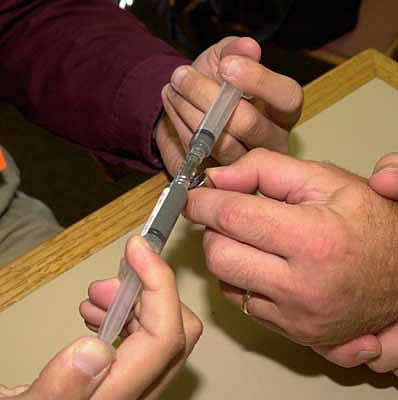
The Lord people have this cool little "Rheonetic Fluid" demo device. It’s a couple of syringes full of water-based MRF joined end-to-end. A small round magnet is included. Work the syringe pistons back and forth then bring the magnet close. All of a sudden you feel resistance. Bring the magnet closer and the syringes lock up. Image: Author |
MRF reacts to changes in magnetic field strength almost instantaneously. The speed depends on how quickly the field can be altered. A MR shock absorber can do that in a couple of milliseconds. The overall, system response is slower but, still, noticeably quicker than any other ride-adaptive shock system in the world. Other hydromechanical systems may have a potentially wide range of damping authority but, in practice, can’t switch rapidly or accurately enough to make such a range effective during high-frequency wheel movement.
Magnetorheological fluid was discovered more than half-a-century ago by the late Jacob Rainbow, a prolific scientist and inventor working for the U.S. National Bureau of Standards. It wasn’t until about 1990, once digital signal processor controls became fast enough and cheap enough, that MRF in automotive suspension dampers became practical. After that, it took Lord and Delphi over a decade to take MRF from a product around which scientists would stand, fingering their pocket protectors, pondering, "Uh yeah, dude, this stuff is sweet. It could work in, like...a shock absorber on a car." to where Mike Neal and I could drive a 50th Anniversary Corvette 120 mph over the worst dip at Milford.
There were countless challenges in getting the fluid to perform well and be durable in a shock absorber. The three most significant were developing it: 1) to have consistent rheological properties over the life of the shock absorber, 2) so its iron particles are not abrasive, and 3) so CIP would not quickly settle out of the fluid when the car was at-rest.
During its commercialization of magnetorheological fluid, Lord discovered the "In-Use-Thickening" (IUT) phenomena. Over a moderate period of time, the surfaces of the iron particles, a mix of iron oxides, carbides and nitrides, would flake away. The debris would suspend in the carrier fluid and, as they accumulated, the fluid would thicken. If the off-state fluid gets thicker; off- and low-state damping become more aggressive but high-state damping doesn’t change, so the range of damping is reduced.
In their untreated form, the abrasive CIP would grind away the insides of the shock absorber and themselves in short order.
Iron is heavier than the fluid carrier, so untreated CIP would quickly settle to the bottom of the shock as soon as the vehicle’s suspension stopped moving. As they settled, they would "clump" together making redistribution of the particles difficult and degrading damping once the vehicle resumed service.
Exactly how Lord solved these problems, particularly IUT, is a mystery. When asked about specifics, Lord Corporation’s Marketing and Sales Manager, Dr. Lynn Yanyo, continued the company’s policy of not commenting, saying those aspects of its product are proprietary, then referred us to some public domain information.
Processes used by the oil refining industry make abrasive substances suspended in liquids nonabrasive. Additives are introduced into MRF which we believe either coat or lubricate, or both, the CIP such that they become nonabrasive. The settling problem is also addressed with additives, though we’re not sure whether they form a coating that makes CIP more buoyant or whether the additive is, are you ready...a "thixotropic agent", which thickens the fluid while it’s at rest such that it resists settling of the particles, but as soon as the fluid moves, causes it to reliquify. Dr. Yanyo is fond of making analogies to food. "Ketchup is thixotropic," she told us, "and, until sheared, it won’t flow. Once it’s sheared (shaken loose in the bottle) it flows easily."
In any event, IUT and abrasion are virtually nonexistent. Lord’s enigmatic, Rheonetic Fluid is, also resistant, but not totally immune, to settling. GM’s durability testing showed that if the car is at rest for a very long period of time, say six months or longer, there can be some settling of the CIP, however, it takes only a few strokes of the shock to agitate the MRF enough that the particles are redistributed and the shock works as intended.
MR Shock Absorber Hardware
There are no valves in a Delphi MagneRide shock absorber. They are replaced by an electromagnet inside the piston assembly of each damper. This design results in a 40% reduction each shock’s parts count.
 |
 |
 |
||
|
Click image for larger view
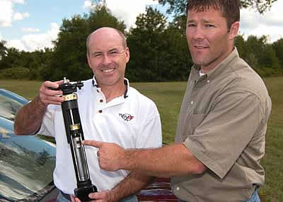
Our hosts for the "Milford MR Show", Darin and Mike, showing off the hardware. Dellinger (right) points out the heart of an MR shock, the magnetic piston assembly. Image: Author |
Click image for larger view
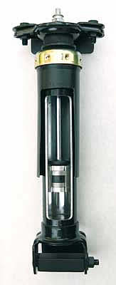
Our friends at GM took a rear MR shock and made this cutaway, demo unit. For clarity, the floating divider piston which normally divides the volume beneath the shock piston has been removed. Image: Author |
Click image for larger view
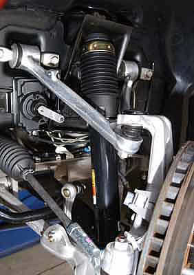
From the outside, this MagneRide shock, on the left front of an ’03 Anniversary car, looks just like most other shock absorbers. It’s basic architecture is similar, too. Image: Author |
The lack of valves also results in smooth, laminar flow of the MRF through the piston. Where traditional shocks are prone to noisy, turbulent oil flow, this laminar flow actually reduces suspension noise. Laminar flow is, also, more predictable, so MR dampers meet design specifications to within a more narrow, 2-3% tolerance.
The rest of MSRC shock architecture is similar to that of a traditional, gas-charged, mono-tube unit. The shock tube bolts to the suspension. The piston rod bolts to the chassis. The rod ends in a piston which moves up-and-down in the tube. A piston seal prevents MRF from bypassing the piston and a piston rod seal keeps fluid from leaking out. At the bottom of the tube, a floating divider piston and seal separates the magnetorheological fluid from a high-pressure gas chamber which pressurizes the fluid to prevent foaming.
Each piston/electromagnet assembly has four channels machined into it. As the piston moves up and down in the shock tube, magnetorheological fluid flows through these channels. When the magnetic field is weak, it flows freely. As the magnetic field gets stronger, the fluid’s CIP, attracted to the magnet’s poles and each other, form fibrous structures altering the yield stress or the "rheology" of the fluid.
This change in yield stress is localized inside the piston channels. As MRF moves into the channels, the CIP align in matrices and, as the fluid exits the channels, the matrices dissipate. The altered-rheology fluid inside the channels restricts flow and dissipates the kinetic energy of the piston’s motion thus absorbing the "shock" of suspension movement.
 |
 |
|
|
Click image for larger view
For this close-up of a MR shock piston, we added a rubber band to simulate a section of the flow of MRF through one of the four channels in the piston. The areas within the red circles are where the magnetic lines of flux pass through the MRF and cause the fibrous matrices to form. Image: Author |
Click image for larger view
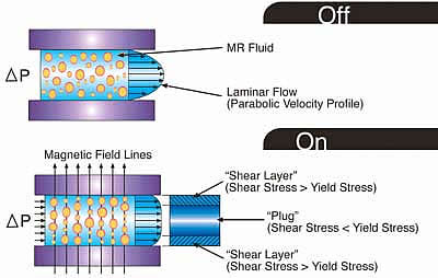
Once the fibrous structures form in the MRF, resistance to flow, or damping, is accomplished by the non-laminar flow though the piston channel. The center "plug" of MRF has not sustained enough shear to exceed its yield strength. This slows flow velocity close to the center of the flow and that resists overall flow. Image: Delphi Corporation |
Lord’s Rheonetic Fluid allows a wide variance in restriction available giving the shocks their wide damping bandwidth. The speed with which the fluid can vary its state makes that wide bandwidth practical.
It’s been widely stated, even in some GM service data, that the magnetic field causes a change in the MRF’s viscosity. In reality, there is no change in viscosity. It is the localized restriction to flow posed by the "plug" of altered-shear-strength, MRF which causes the damping.
Ok. We’ve got shocks full of Star Wars MRF, so what’s next?
The Deep-Geek of MR: the "Sky Hook" Algorithm
We need a way to control the magnetism produced by each shock piston so MSRC can apply its variable damping in a useful manner. Since I’ve described the needs of the system in a sentence, don’t get the idea that developing MR’s controls was easy. It took scores of people, hundreds of millions of dollars and a decade of research and development to perfect Magnetic Selective Ride Control and the lion’s share of the work went into the last word in the name: "control."
MR’s position sensors measure each wheel’s movement. With that data, the controller determines three types of body motion: pitch, roll and heave. "Pitch", (front end moves up or down) and "roll", (the car leans), are terms most of us have heard before, but "heave" might be a new one. When the car heaves, both ends move the same way. If you drive over a rise, the body heaves up, then down.
 |
 |
|
|
Click image for larger view
This is a position sensor at the front of an 03 MR car. There are four of these on the car, one at each corner. They send data to the MR controller... Image: Author |
Click image for larger view
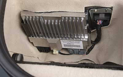
....located at the back of the car. Image: Author |
The sensors sent that information to the heart of MagneRide, is its controller, located in the driver-side storage well at the rear of a C5. It’s a powerful, dual-processor device capable of making 1000 adjustments per second in each of the car’s four shocks. At highway speeds that’s a damping change about every inch the car moves.
MagneRide, also, uses brake, throttle, steering angle, lateral acceleration and vehicle speed data. MR even senses air temperature about which, Darin Dellinger told the CAC, "Much like all the other sensors that contribute to the intelligence of the MR system, temperature gives us the ability to adjust damping for low and high temperature operation. It’s no secret that a car’s character, in general, may change with temperature extremes (because of rubber parts, etc.). We can use temperature information to make the car’s ride performance more consistent over its entire operating range."
 |
|
Click image for larger view
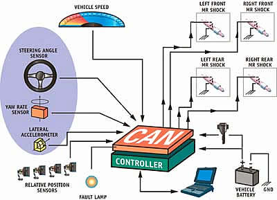
The basic components of Magnetic Selective Ride Control. Image: Delphi Corporation |
The MR controller processes sensor data with various software "algorithms" An algorithm is a set of steps for solving a problem. To be an algorithm, a set of steps must be unambiguous and have a clear stopping point. The different algorithms MR uses fill a thick book.
Back in ancient times-the end of the 1980s, GM had a major program to develop active ride or "Active Suspension" as it was to be called. GM got very close to releasing active ride as a ZR-1 option. A dozen or so development vehicles were in validation, the Owner’s Manual had been rewritten to include Active Suspension but, just before production began in early 1990, GM pulled the plug.
By definition, an active ride system applies kinetic energy to the suspension to counteract ride movements whereas passive ride systems, which even MagneRide is, only provide damping-sophisticated damping perhaps (marketing guys love to call it "semi-active" suspension) but nevertheless, MR is still passive damping.
In the mid-’90s, I tested the remaining drivable Active ZR-1 at Milford. It was pretty amazing to drive. Bumps, dips and so forth were almost nonexistent. Unfortunately, problems such as: ride harshness, weight, service-complexity, high cost, engine power loss due to a big hydraulic pump and service hazards related to the flammable, high-pressure hydraulics used by the system had GM killing the program. For those planning a trip to the National Corvette Museum, there is an interesting Active Suspension exhibit there.
The passing of active wasn’t a total loss because it provided significant ride control software which was refined then used in RTD for MY96 and CVRTD for MY97. Active knowledge and additional experience gained with RTD was, then, rolled into Magnetic Selective Ride Control.
When we talked about MR shock tuning with Mike Neal, we heard a lot about "sky hook" which is one of the system’s more important algorithms. Sky hook is the strategy focused on isolation and body control. It gets its name from the idea that, if the car could be hooked to the sky, it would ride nice regardless of how nasty the road gets but "sky hook" is not a literal term. As good as MR is, it cannot isolate the car completely.
We interviewed Darin Dellinger and Mike Neal extensively for this article and the most interesting dialog between them and the author concerned algorithms.
"Included in the enormous amount of intellectual property we’ve generated with our ride control system work," Darin Dellinger said, "we have one patented algorithm which uses four wheel position inputs to determine the body’s heave, roll and pitch."
"This is the sky hook algorithm," Mike Neal added. "It’s one of MR’s main algorithms. Based on that, MR commands some force level at each shock, separate at each corner and specific to compression or rebound damping. This is done in an attempt to make the car not heave, pitch, nor roll.
 |
|
Click image for larger view
Delphi’s Darin Dellinger and GM’s Mike Neal, shown here during a discussion between they and media members off-camera about algorithms, are two of the movers and shakers in GM’s effort to put MagneRide on Corvette. They are backed up by scores of other design and development engineers at Lord, Delphi and GM. Image: Author |
"Sky hook is a body control algorithm. We have other algorithms for wheel control, which will give us different damping forces. Separate from those fundamental algorithms, we have a whole bunch of others. For instance, if you’re getting to the end of the travel, we have algorithms which recognize that then do something to reduce impact on the bump stop. We have algorithms that compensate for temperature. We have algorithms which condition the signal to smooth transient spikes and things like that."
DD: "it’s one thing to know the heave, roll and pitch of the body and wheel motion but it’s quite another to figure out what’s most important to damp at what time. Very generally, we separate our software into four different areas: body control, wheel control, stability enhancement and end of travel conditions."
MN: Over the years, these algorithms evolved and we added new ones. Some were fundamental algorithms. Others were to address shortcomings of the previous system (CVRTD) because it wasn’t quite as fast, quite as strong or broad in bandwidth"
DD: "For example, during early CVRTD development, we invented an algorithm which solved a control system instability that would cause the car to pitch. It was a huge pitch...you could not miss this pitch. We had to come up with a strategy to detect the road conditions which caused that pitch then to correct the control system instability.
 |
|
Click image for larger view
It was at this point in the discussion that Neal and Dellinger blamed having to develop the LA Freeway Hop algorithm for the old RTD on the author, because that he lives in the vast suburban wasteland that is Southern California. Image: Author |
MN: In fact, we discovered this out in your (the author’s) area, out in L.A."
DD: "Yeah, ’L..A. freeway hop’."
MN: "We came up with an algorithm specific to your neck of the woods."
DD: "It was crazy how noticeable this pitch instability was. It would make the car go to end-of-travel during pitch oscillations."
MN: "It would almost make the car feel like you were putting energy in-like an active car that wasn’t doing the right stuff. This problem was so challenging, we duplicated that kind of road surface at our (Mesa, AZ) Desert Proving Ground.
"A good thing about MR is, because it’s so fast and so much more powerful in it’s damping force than our previous systems, we’ve been able to eliminate a lot of conditioning algorithms in our calibration of the Corvette."
 |
|
Click image for larger view
Image: Author |
Once MSRC’s sensors have gathered data and its controller has processed it with the proper algorithms, four electrical drivers vary current flow to the electromagnets in the shocks which control the magnetorheological effect to provide the correct damping. This could be damping to improve ride, to improve handling or it could be to limit front end lift during acceleration or dive during braking. The MR controller networks with the Active Handing/ABS/Traction Control computer and, if AH intervenes, MR might change damping to further AH’s contribution to the car’s handling.
"Delphi refers to this interaction (between systems such as MR and AH) as ’UCC’, or ’Unified Chassis Control.’" Darin Dellinger stated. "In the past, we (GM and Delphi) have generally called this stuff ’Vehicle Stability Enhancement’. Suspension and brake control systems are only one subset of an integrated system that could potentially include suspension, brake, and steering systems."
One change for 2003 is the selector switch, a fixture of Corvette ride-adaptive systems since 1989, now has only has two positions. In the "tour" position, the MR controller emphasizes the sky hook algorithm when setting shocks and when set in "sport", it emphasizes wheel control.
The Bad Dip, Inch-by-Inch
Enough of the deep-geek stuff. Let’s go back to the R/H Loop at Milford and examine what Magnetic Selective Ride Control does when one traverses the "Bad Dip" at 120 miles per hour.
 |
|
Click image for larger view
Mike Neal offers a blow-by-blow...oops...bad words...let’s say, a millisecond-by-millisecond account of what MR does when the car crosses the Bad Dip. Image: Author |
First we need to know how much ground is covered in a given time. At 120, you’re covering 176 feet every second. MR takes about 10-mSec to respond and in that time the car only moves 21 inches. From here on, the best guy to explain what happens is Mike Neal.
"In a basic sense, MR tries to maintain body movement in a plane in space as the car moves forward. Calculations taking place in the controller are always trying to achieve that end.
"When you enter the dip, the wheel position sensors, seeing the wheels falling down into the dip, give a signal to the controller that a large body event is taking place. The controller determines the next thing the body will do is pitch down.
"Before the body can be pulled down, MR goes very soft on the rebound damping, not only to let the wheels fall into the dip, but to let the springs actually push the wheels into it. Without MR, you’d have heavier rebound damping which would tug the front end into the dip. MR avoids that by turning down the rebound. Again, sky hook is trying to keep the body in a flat plane.
"Once the tires near the bottom of the dip, the body wants to fall into it, too, so MR gets very stiff on the compression damping. It takes much longer for the body to move down on the suspension because compression damping is, now, very stiff.
"When you start coming up, out of the dip; the controller sees the suspension starting to be shoved up into the body. To keep the body from pitching upwards, sky hook sets the shocks very soft on the compression side, so the suspension will easily move up but not pitch the body up as you come up, out of the dip on the other side."
Consider carefully what Neal just said: as the car starts out of the dip, Magnetic Selective Ride Control switches through nearly its full range of compression damping, from very stiff to very soft. It does this in around 10 milliseconds while the car, traveling at 120 mph, moves about two feet...amazing!
"As you finally clear the dip," Neal continues, "you might have some, secondary, cyclic motion taking place which pitches the body. The controller sees that, sky-hook-calculates, then applies whatever appropriate level of compression and rebound damping to properly damp those motions."
"This is just what the body control strategy is across this one bump. At the same time, the system may be doing wheel control and stability enhancement, too. MR’s actions are never simple. It can be using several different algorithms to control varied types of suspension movement simultaneously."
Star Wars? Rocket science? You bet.
 |
|
Click image for larger view
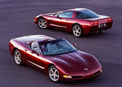
Magnetic Selective Ride Control was standard on all 50th Anniversary cars and optional on any 2003 Coupe or Convertible. In ’04, MR is an option on coupes and convertibles. Image: Chevrolet Communications |
On the Road with MR
Blasting across dips at 120 is an extreme exhibition of Magnetic Selective Ride Control’s abilities even borderline-crazy C5ers shouldn’t try at home. So, what kind of driving will make you glad you ordered MR on your 2003 Coupe or Convertible?
"If you’re on a smooth road," Mike Neal told us, "while you’ll notice better isolation, it’s advantages to handling are minimal. It’s on roads which cause large ride events and body motion where it has huge benefits.
"If you’re trying to get around a track that’s smooth, like Road America, a ’billiard table’ having no great heaves and undulations, MR has a minor effect.
"But, go to a place like the Nürburgring in Germany where it’s like the asphalt was laid down after little or no grading or smoothing-lots of dips and undulations-and you’re takin’ every turn at 100 mph or faster. It doesn’t take much of a ride event to really unload the car by heaving it, pitching it around and rolling it. In a place like that, MR is a huge advantage.
 |
 |
|
|
Click image for larger view
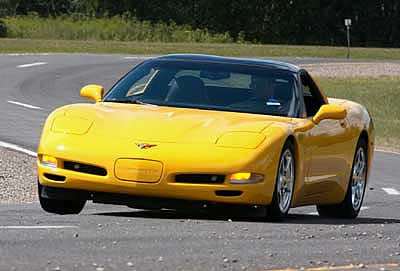
MR doesn’t offer the sporting driver that much on a flat track, like this section of the Milford Proving Ground, other than a little less body roll in transitions as MR dials-up the roll damping. Shown here is Darin Dellinger at the wheel of a base 03 Coupe. Image: Author |
Click image for larger view
At about the same spot on the track we see Mike Neal in a 50th Coupe with MR. Note less body roll. Image: Author |
"With MR, you don’t have to wait for the body to settle before making your next steering input because the car is already transitioned, ready for the next maneuver. In that kind of ride environment, MR greatly improves the Corvette’s handling."
Nürburgring, huh.
Uh well...that ain’t in the CAC’s budget this month. Nevertheless, to fully appreciate MR, I had to find something beyond structured tests at a proving ground in Michigan.
Two thousand miles southwest, I found that on roads I know well. North of the coastal town of Carpinteria, California are the Santa Ynez Mountains. A little southeast of "Carp" you’ll find the beginning of California State Route 150 which zig-zags its way into the Santa Ynez hills towards the resort town of Ojai. At Ojai, get on SR33 going north and a real thrill ride begins over a circuitous route through the higher parts of the Santa Ynez range. Nearly two hours later you’ll roll into the Central Valley town of Maricopa having been over 90 miles of some of the better roads for high-speed touring west of Nürburgring.
This was a route I knew well and the perfect choice to see how MR works in the real world, but I didn’t have a car to test because, as is sometimes the case because of recent budget cuts, General Motors Communications had no Corvettes in its media evaluation fleet for us to use. We borrowed a privately-owned 2003, 50th Anniversary Coupe and its owner, Corvette Club of Santa Barbara member, Paul Mariano, for our blast over the Santa Ynez range.
 |
|
Click image for larger view
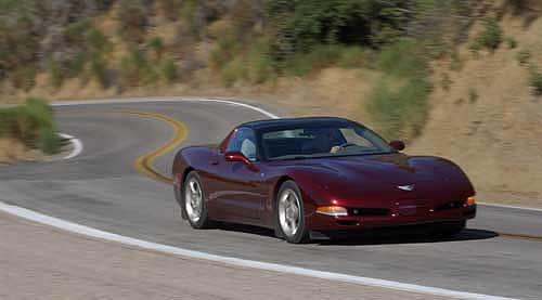
Paul Mariano, at speed on State Route 33 in Southern California’s Santa Ynez Mountains. Star Wars meets the 50th Car...in the real world. Image: Author |
SRs 150 and 33 had plenty of heaves and undulations of different depths, heights and lengths. There were even a few Nürburgring-style, bumpy, 100 mph turns, too. On the run over to Maricopa, it was easy to feel Magnetic Selective Ride Control doing its thing. Compared to a base car, it was like night and day. Considering this was a performance sports car, the ride was quite plush and the isolation quite good.
Even compared to the previous RTD system, MR has improved wheel control over the higher frequency (10-15 Hz) ride movements because it can bring more damping authority to bear and it can switch between damping levels quicker. The system effectively damps the big heaves, pitches and rolls that come from bumps and dips or low spots on the edge of the road. If dips at the Grounds weren’t enough, the hard run to Maricopa sold me on MagneRide.
Does MR have short comings? Really high frequency (17-20 Hz or better) stuff, such as little ripples on concrete highways or washboard/chatter-bump surfaces are a slight problem. In a straight line, the ride is a little harsh and, when ripples’ frequency approach that of the vehicle structure, you can hear kind of a subdued rumble. At high speed and at high lateral acceleration over chatter bumps, the car wants to skate sideways.
MR seems to be less effective in damping this kind of harshness presumably because, even with a 10mSec response, with the car moving fast, it can’t react quick enough to bring the most ideal damping to bear. While this harshness is a shortcoming, the types of surfaces that cause it are fairly rare.
In fact, this might not be entirely an MR issue. The stiff sidewalls of C5s run-flat tires amplify this type of harshness to the suspension. Rumor has it that C6 will have a new, Goodyear EMT with vastly improved harshness qualities and that might solve this problem.
On relatively smooth roads near the car’s limits in abrupt transitions and turns at high lateral acceleration, a MR car’s base springs and stabilizer bars show their inadequate roll stiffness. Sources tell us that DIY tuners can trade a little isolation to make up some of this roll stiffness deficit by adding Z51 stabilizer bars to MR cars. A C5 in the hands of a talented, aggressive driver will react well to that change.
Hard core racers, autocrossers and very aggressive street drivers will still want either Z51s or Z06es, both of which have higher rate "stab" bars along with stiffer springs and fixed-valve shocks tuned specifically for motorsports.
After all this discussion of MagneRide, I keep coming back to this one, overriding and persuasive thought: It’s pretty damn amazing to be able to drive a C5 really hard into a high-speed sweeper on a rough road and not have the car upset by bumps, dips or rises. Yeah, you might get ABS and even see a little Active Handling, but the big thing that makes the car more predictable and handle so well when going really fast over rough stuff is MR.
Clearly, we are not the only ones who think this. Popular Science magazine announced Magnetic Selective Ride Control as the winner of its prestigious "Best of What’s New" award in the Automotive Technology category for 2002. This award recognizes products or technologies that are a significant step forward in the category. The December 2002 issue of the Society of Automotive Engineers magazine, Automotive Engineering International, named MagneRide one of its "Top 10 Technologies" for 2002.
Award-winning Magnetic Selective Ride Control-yeah, a bit Star Wars it is, but it sure works well.
The Corvette Action Center and the author would like to thank Team Corvette’s Mike Neal and Dave Caldwell, Delphi’s Darin Dellinger and Beth Lewis and Lord Corporation’s Dr. Lynn Yanyo for special assistance in preparing this article.