I’ve had a problem with the photocell in my ’84 cluster since I bought it. During the day the cluster is too dim to see...unless you turn the park lights on. What I did temporarily to "fix" it so that I could see the thing during daytime is take the cluster apart and "jumper" the photocell leads together...but this disables the ability to dim the cluster at night with the headlight switch dimmer.
So...I took the cluster out again and started experimenting with some different photocells (it’s on my workbench connected to a benchtop power supply). What I found that works pretty good is a photocell that Radio Shack stocks in most stores. It’s actually in a "kit" of 5 different photocells. The kit part number is 276-1657. There are three small cells and two large cells in the kit. The one to use is one of the smaller ones...to select the right one use an ohm-meter and use the one that measures the highest resistance. Make SURE that the ambient light does NOT change when you are measuring the resistance of these cells. Even a slight shadow will effect the resistance of the cell.
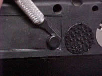
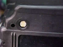
Replacing the bad photocell can be done without removing the LCD driver board from the cluster, but you will have to remove the CPU board. You will also need to remove the clear plastic cover over the photocell from the front of the cluster. Use an xacto knife to pry the plastic plugs out:
Using a good soldering iron and some solder wick, de-solder the old photocell and it can be pulled out of the front of the cluster (tip - put a little solder flux on the wick and it will work MUCH better).
Once the solder is wicked up from around the pin, it should look like this (the left one):
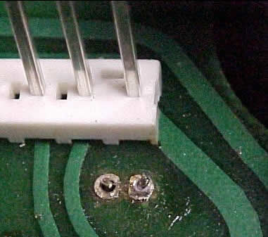
With a pair of tweezers you should be able to move the pin around inside the thru-hole in the board…that’s when you know the solder has been removed. Be careful not to apply the heat of the soldering iron too long or the pad will lift off of the board, 5 seconds or so at a time should be enough.
Once both pins have been de-soldered the old photocell can be pulled out from the front of the cluster.
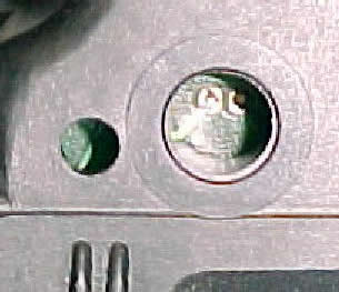
Once the old photocell is removed you will notice that the Radio Shack replacement is quite a bit larger than the old one. It will fit nicely in the hole in the cluster, you just won’t use the plastic shroud that the old one did.
Before installing the new photocell a series 68K ohm resistor needs to be soldered to one of the photocell leads (it doesn’t matter which lead, the photocells are non-polarized resistive devices). Cut one of the leads down leaving just enough to solder the resistor to.
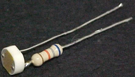
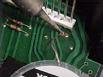
Then just insert the photocell/resistor assembly into the hole in the front of the cluster and push the leads through the holes in the LCD driver board. It’s a little tricky to get the leads lined up with the holes in the PCB board. Again, it does not matter which lead goes to which hole in the PC board. Once the photocell/resistor combo is in it will look something like this:
With the series resistor the cell will not sit all the way back in the hole in the front of the cluster. In this picture I used a ½ watt resistor (that’s all I had). If you use a ¼ watt resistor the photocell will be able to sit a little deeper in the hole.
Solder the new photocell leads in place, trim them off and you’re ready to put it all back together.
Here are some specs on the Radio Shack part (manufactured by Hamamatsu)