Is this a Dream or is that really my LS7?
CAC Does the Corvette Engine Building Experience - Page 6 of 10
by Hib Halverson
© September 2012
No use without permission, All Rights Reserved
Click on the images for expanded views - it's much easier on the eyes.
From there, it was onto the timing chain, oil pump assembly,
front cover and, finally, the oil pan but, with the LS7, oil pans are,
well...complicated. Actually, it's a "dry sump pan" because, when the
engine is running, there's little or no oil in it. Gone are the days when we
could just run the pan bolts down and be done. Starting back in '97, to stiffen
the powertrain and reduce NVH, the block, pan and clutch or torque converter
housing are bolted together, both top and bottom. In order for that to work
well with the block and pan having the same load applied once BG Assembly adds
the clutch housing, the oil pan and block have to be held rigidly by a fixture
while the pan bolts are tightened and then, once they're tight, the
relationship between the block and pan has to be checked with a dial indicator
which attaches to that fixture.
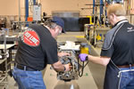
Image: Mark Kelly/GM Powertrain
Timing chain assembly goes on. Never let it be said that single row chains are not for performance applications. They work just fine on 7000 rpm, 505-hp LS7.
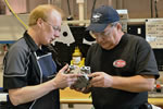
Image: Mark Kelly/GM Powertrain
Mike and I discussing the oil pump. A pretty cool design. GM added a second stage to the existing wet-sump oil pump then lengthened the crankshaft snout, which drives the pump.
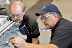
Image: Mark Kelly/GM Powertrain
Once the oil pump is in place, the front cover is installed. Here we are lining up the cover to the block using an alignment fixture-that's the flat black plate under the socket wrench.
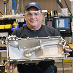
Image: Mark Kelly/GM Powertrain
Here's the dry sump pan. One stage of the oil pump scavenges the pan through the oil pick-up-the upper single hole-and sends it to the oil tank-middle hole. The other stage sucks oil from the tank and pumps it through the oil filter and the oil cooler and then to the engine's oiling system-lower hole.
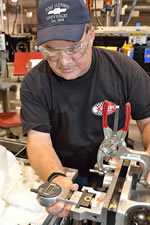
Image: Mark Kelly/GM Powertrain
Once the pan is on the block and the bolts tight, we used this dial indicator device to measure the relationship between the clutch housing mounting faces on the pan and the block.
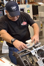
Image: Mark Kelly/GM Powertrain
Next to go on-the coolant/engine oil heat exchanger. It helps warm the oil when the engine is cold and it cools the oil when the engine is at operating temperature. This part was originally an LS9 piece, but, for the 2011 model year, the Z06's oil-to-air cooler was discontinued and replaced this unit. In fact, it's a new spin on an old idea-the 1985-91 Corvette Z51s and Z07s had a coolant/oil heat exchanger.
Lifters go in next and they're installed in "racks" of
four. The roller hydraulic lifter used in an LS7 is the only part in a Gen 4 V8
with a design which carries all the way from the Gen 1 small-block. Other than
slight differences in oil metering rate and plunger travel, it's changed little
since it was introduced for the 1987 model year. It was sorta weird, a part
which dates back a quarter century, but I guess that speaks to the soundness of
the design.
Image: Mark Kelly/GM Powertrain
We did a lot of cart rolling during my day at the PBC.
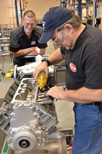
Image: Mark Kelly/GM Powertrain
The LS7's hydraulic roller lifters get a squirt of oil then are installed in racks of four. Engine Builder, Bruce Bloomfield watches and chats-"Are you car magazine guys really allowed to make up words?" Just kidding-he really didn't ask me that.


