Ruthless Pursuit of Power: The Mystique of the C6 Corvette LS7 Engine - Page 10 of 26
Ruthless Pursuit of Power: Lucky Seven Edition: The Mystique of the 7-Liter, 7000-RPM, LS7 - Page 10 of 26
 |
 |
by Hib Halverson
© May 2013— Updated: November 2014
No use without permission, All Rights Reserved
Cylinder Heads
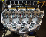
One of GM Powertrain's strong points is its ability to engineer really great cylinder heads and, the LS7 clearly demonstrates that ability. A forged crank, Ti rods, lightweight pistons and dry sump oiling are neat stuff in any performance car, much less one of the Vette's price range, but, from a performance standpoint; the most significant pieces of LS7 hardware are its cylinder heads.
Although C6 debuted in 2005 with the LS2, Gen 4 Small-Block V8 under the hood, the LS2 head was a actually a Gen 3 hand-me-down, having been used on the 2001-04 LS6. The LS7's head was the first Gen 4 head to go to production and if there had been a mission statement for its development, it might have been: "maximum performance with minimum complexity".
In late-Summer, 2003, the Society of Automotive Engineers magazine Automotive Engineering International published an article about a head with three valves-per-cylinder being part of a "...500-hp, Corvette engine". Math art in the AE article and photos which appeared on the Internet later showed complex pushrod valve gear. This article sparked speculative chatter on Internet forum sites along with articles in other magazines, such as Corvette Enthusiast, suggesting a 24-valve engine would be in the "next" Z06. The AEI article on the 3-valve head is reproduced elsewhere on the CAC at https://forums.corvetteactioncenter.com/threads/press-gm-smallblock-gets-three-valve-head.36183/.
While the the "3-valve" had been under development by GM's Advanced Powertrain Group and might even have been a last-ditch attempt at getting 500-hp out of a 6.4, it was never a part of the LS7 program. The team at Powertrain working on the seven-liter stuck with the two-valve configuration which had worked so well with the LS1, -2 and -6 engines. In a discussion of the three-valve head, Jordan Lee, who's now Chief Engineer for Small-Block V8 Engines, told the CAC, "Our philosophy is not to add technology for technology's sake. If technology is really not a performance benefit, we won't implement it." As such, the three-valve head became part of the LS7 mystique and another curious footnote in Corvette engine history.
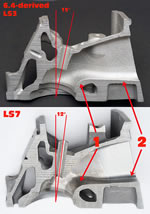
Using computer analysis tools, port models in "flow boxes" and single cylinder test engines, the cylinder head team, under Design Responsible Engineer, Dennis Gerdeman, developed and tested a multitude of intake port, exhaust port and combustion chamber shapes before ordering any prototype LS7 parts. This process added two more big architectural changes to the square ports and revised pushrod locations developed for the Six-Four head. First, valve angle was decreased from 15° to 12°. Secondly, intake port was raised. Its floor was lifted 9-mm. (.354-in.) and its roof was raised 5-mm (.197-in.), for an overall cylinder head height increase of 7-mm (.284-in.). These changes improved air flow. Also, at this point in the development, combustion chamber displacement was set at 70-cc's. For this article, the CAC recorded a long interview with Dennis Gerdeman. It began with a discussion of the early LS7 head work.
"We were working on this (6.4L LS6 successor) and they gave us a target (450-hp) and we achieved it early in development," Gerdeman told us. "It wasn't long after that when (GM upper management) came back and said, 'We need to raise the bar and increase our target to 500 horsepower.' It was really late in the development stage and that sent us all scrambling. That's when we started pulling out all the stops--the bigger bores, the titanium rods and inlet valves--and really stretched the limits of the Small-Block.
"It was (early) 2004 when we were going through this accelerated development crunch. A lot of it was hardware. When we were looking strictly at air flow, we were doing a lot of work on the air flow bench, nearly all of it with single cylinder flow models. From an air flow analysis standpoint, we were very limited back then. We weren't nearly as developed in CFD (Computational Fluid Dynamics) analysis tools as we are, today."
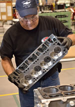
The head is cast of 356-T6 aluminum by Nemak using the semi-permanent mold process and cold-box cores. For machining, the head is shipped to the same Linamar facility which does the block. An LS7 head is machined entirely by five-axis, Computer Numerical Controlled (CNC) machining centers having automated tool changing. The use of 5-axis CNC allows all machining operations of critical head features--ports, chambers, valve seats and the deck--or "joint surface" as cylinder head engineers say--to be accomplished with no set-up change between them and that enhances the accuracy of the machine work. We asked Dennis about the decision to use all CNC machining for the LS7 head.
What's this five-axis stuff, anyway?
by Hib Halverson
© May 2013— Updated: November 2014
No use without permission, All Rights Reserved
Five-sided machining, also known as "3+2", is the process of setting up a part one time and machining five sides using a 5-axis, Computer Numerical Control (CNC) machining center instead of machining the part one side at a time using a conventional 3-axis machining center.
Full Story: What's this five-axis stuff, anyway?
"The Engine Power Analysis Group told us, 'You're gonna need such-and-such air flow to have a chance at 500 hp.' We had a good feel for the geometry we needed for the perfect transition from the ports, across the valve seat and into the chamber. We also needed to reduce cylinder-to-cylinder (air flow) variation and you just cannot get there with a conventional casting and machining process.
"With conventional castings--and we have some excellent casting suppliers--their variation is too high to ensure those perfect transitions. With conventional plunge machining of the valve seat and casting draft (note: "draft" is the slight taper, perpendicular to parting lines, required with sand-cored features of semi-permanent mold castings, such as ports. This "core draft" is required in order to extract the sand port cores from the steel tooling in which they are created.), you can't get those perfect transitions. That's when we decided to CNC. At first it was the chambers and the valve seats but then, looking at the ports, we said, 'There's no way to get the airflow we need without CNC machining there, too.' The only way to get that is to do an unconstrained, three-dimensional, CNC'ed port shape.
"We have the seats and guides installed. They CNC the ports, chambers and seats in the same machine set-up. There's no stack-up from fixture-to-fixture--little or no variation from the CNC porting, to the seat machining and to the joint surface, so our chamber volumes and our seat machining transitions are as good as you can get. It all comes down to the repeatability of CNC machining. Any variation from that is very, very small."
Other subjects Dennis and I covered were how Katech's C5-R engine program influenced the LS7 cylinder head development along with valve unshrouding. Finally, we got into Mike Chapman's work.
When a valve opens, there are parts of the valve opening which are closer to the combustion chamber or cylinder bore walls than the rest. The closeness of these walls is called "shrouding" and it restricts air flow though the valve opening. Obviously, the more you move the valve opening away from the chamber or bore walls--i.e.: "unshrouding" the valve--the less restriction there is and the better your air flow will be.
"We went to the C5-R guys at Katech and looked at their valve geometry, sizes, positions relative to the bore walls and we decided that was a great place to start," Gerdeman continued. "We took the Six-Four head and kinda melded it into stuff that we gleaned from the C5-R. We still had to start with the Six-Four head because there were certain manufacturing limitations far as geometry and production durability. The C5-R. started us down the path of siamese valve seat inserts, which was a real unique feature for us--something we'd never done before. The siamesed seats were driven by the valve size and getting maximum unshrouding from the bore wall. We were making a lot of prototype flow boxes that we could measure on a flow bench and playing with different configurations but, until we went siamesed (and unshrouded the valves); we just weren't getting the air flow we needed.
"We had transfer machining lines at the time. On a transfer line, trying to change things like valve angles and locations is impossible without huge investment. We decided, with this volume, to go with an outside machining company. After sourcing, it turned out to be McLaren which ended up (Sept. 2003) getting bought by Linamar.
"McLaren had worked with Chapman Racing. They said, 'Hey, talk to Mike (Chapman) and let him take a stab at this thing.' We had already developed a siamesed layout and what we thought we wanted for unshrouding and valve sizes. Chapman started working through the intricacies around the valve seat, the angles, the blends to the port and the port's geometry around the valve guide. He did a lot of tweaking of port shapes. At the time, we were pretty happy with our intake flow--Chapman did a couple little tweaks there--but he spent a lot of time on the exhaust valve seat and port."
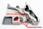
Next we got into a long discussion about various design features of the LS7 which contribute to its performance. The first subject Dennis covered was the all-important short turn radius which, for those who are learning cylinder head nomenclature, is where the port floor curves down, then transitions to the valve seat.
"From an inlet standpoint, it's the height (of the port), the shape of the short turn and the area schedule--how the (cross-sectional) area changes as you go down the length of the port--that's important. We spent a lot of time developing the short turn and from a CAD standpoint, it was a lot of complex geometry because, whatever we ended up with; we had to have a CAD model.
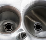
"Another focus was the shape of the seat insert after CNC machining and its transition across the 45° valve seat and into the chamber. Making those transitions as smooth and as much like a radius as possible as they come out of the port and into the chamber is another key feature, but you still need a very defined flat for the valve seat, itself. There are four angles plus a radius. The fourth angle blending into the radius is very subtle. This radius is different on the short turn side than it is on the long turn side. The short turn, the long turn and even the sides: they're all a little different--another advantage of CNC machining. If it's a cast port or an as-cast seat insert, you are driven to the same geometry all the way around.
 |
 |
